Notifications
Clear all
MONTAGE Series Synthesizers
5
Posts
3
Users
0
Likes
994
Views

Topic starter
In the FM-X Part 2nd LFO, there's a curve shape setting of Sine. When you choose that curve, the Montage display shows you two curves: a red one, and a blue one (see screenshot above).
There's a cryptic note about this in the Reference Manual on page 138:
NOTE When “Sine” is selected, two waves will be shown in the diagram on the display because of the phase shift of the Amplitude Modulation wave.
Between this note and experimentation on my part, I think I've figured out that the red curve shows what happens for Amplitude, and the blue curve shows what happens for Pitch and Filter.
Am I right about this?
Also, I think it would be a good idea to change the user interface so that the labels for the three potential targets of the 2nd LFO were color-coded to match the colors of the curves.
At this point, I'm starting to think there's a level beyond scuba diving: 🙂

Posted : 16/01/2018 5:12 am

I think you are attempting to make this something very literal (software engineer in you)... thanks for the opportunity to discuss and explore this particular Control Matrix...
"Phase" is important to understand. On the 'micro' level. Let's start with the General category; that it is a function of being a delay.
Two identical signals... they are identical in every way. Played together hardly noticeable change to our ear.
Delay the start of one of them ever so slightly you now have a phase issue.
Increase ever so slightly the frequency of one of them, you have a phase issue.
Increase ever do slightly the amplitude of one of them you have a phase issue
Our ear/brain delight in the undulating change in the sound. Picture a gym where you pick up two identical lengths of rope attached to a wall. You send waves rippling down each... when they are exactly sync'd that's "in phase". If one is slightly ahead of the other - even though all other things are the same, they are "phase shifted"... to our ear/brain when this happens with sound... this is instantly noticeable. What it looks like is secondary, primary here is what it sounds like. The very slightest difference in phase of sound waves, is immediately detectable. And not just for musical sounds.
Our ears (2) are positioned on opposite sides of the brain ...specifically we, as humans, use Phase in such a fundamental way to help us pinpoint, locate and recognize millions and millions of different sounds. The very slightest change in phase is detectible.
Varying the phase of the pitch means you are going to change how frequent (how many ripples in one rope) compared to the other
Varying the phase of the amplitude means you are going to change how intense (how much energy is applied to one rope) versus the other
Those are independently applicable. To understand this in the synth engine please... Try this experiment:
Start with an Init FM-X which will be a single Sine Wave active... al we need to illustrate the green line and red line.
This way we can zoom in and know exactly what these parameters do
Press [EDIT]
Press [PART SELECT 1]
Touch "Mod/Control" > "2nd LFO"
Set the "LFO Wave" = SINE
KEY ON RESET = On
Speed = 0
Phase = 0
Delay = 0
Under "Destination" set the Pitch Modulation ... Depth = 99
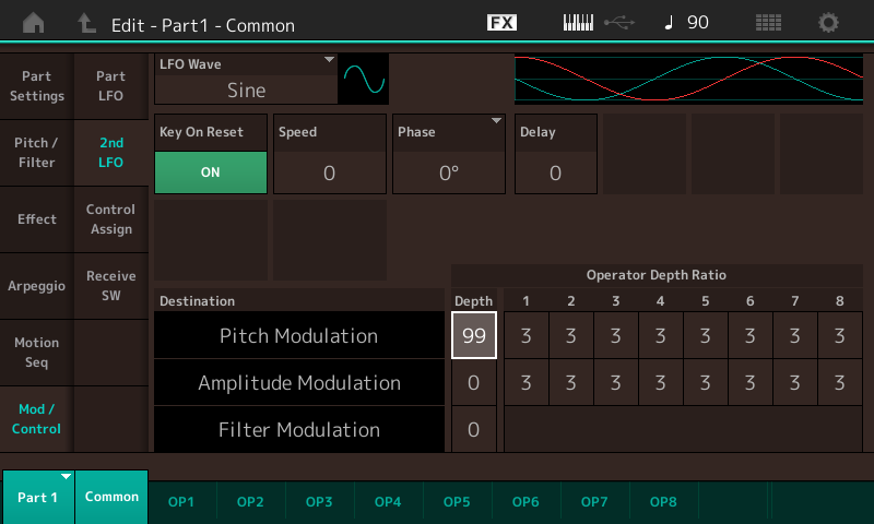
At this lowest and slowest settings you can see, follow and hear the Modulation clearly. Simply hit and hold a note. The green line will represent what we hear initially concerning Pitch movement. Starting at the centerline it travels down to the nadir (lowest point; 90 degrees); it then travels back to the centerline (180 degrees); it then rises to its highest point (270 degrees) before returning to the centerline... that is the complete 360 degree cycle of the Sine Wave. Each complete tour equal "one period". Our ears verify this movement because we hear the pitch change as indicated.
With the Operator's Pitch Modulation Depth Ratio at the default 3 you get significant Pitch variation. (Recognize musically speaking pitch changes are generally small changes).
At this setting change the Phase to "90 degrees" and retrigger a note.
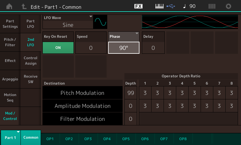
Observation that the Pitch movement now starts at the nadir (the lowest point) and moves up initially. So phase immediately influences the direction of movement
At a setting of "180" the Pitch movement begins normal but rises from the centerline. Total opposite direction from 0 degrees
At a setting of "270" the Pitch movement begins at the high point ...
Doing the same experiments with the Amplitude Modulation Depth set to 99 (follow the red line) you can see that the Amplitude which we perceive as loudness at 0 degrees is at maximum;
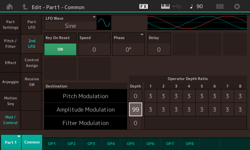
only when the red line is above the centerline is the Operator audible. Start a Note, the volume starts down initially and disappears.... coming back later in the cycle.
So at “90 degree” offset the loudness starts down from the normal start point of nothing, (the centerline is no sound), and so on.
So literally, the green line, when Sine is the selected LFOWave, represent Pitch movement. And the red line represents change in Amplitude. It’s obvious when we slow it down and zoom in on it as we’ve done here ... now increase the Speed of the LFO to understand its impact when used in a musical context. Movement within a sound makes it richer, more lush; perfect is some times less interesting than a bit of phasing. It’s subjective.
Hope that makes it clearer.
Btw- There are no individual Operator Depth offsets for Filter Modulation because in FM-X, the filter is applied to the entire FM-X sound as a whole. In original DX FM engine there are no Filters. Timbre change in original FM is a function of the relationship between Modulator Index as ultimately applied to a Carrier.
Posted : 16/01/2018 3:20 pm

So
Green = Pitch
Red = Amplude
... and color for filter modulation is not described. Assume red with a 50% chance of being wrong.
Posted : 17/01/2018 12:10 am
Topic starter
... or blue/green with that same 50% chance of being wrong.
Bad Mister, could you tell us which color it is for Filter Modulation?
I appreciate your providing the kind of detail that the software engineering mind needs. Thanks…
Posted : 17/01/2018 2:44 am
Topic starter
By experimentation, I just figured out that Filter Modulation is controlled by the green/blue curve.
Posted : 17/01/2018 5:27 am
