
Mastering MODX: An FM-X Exploration, Part II
Mastering MODX: An FM-X Exploration, Part II
This article references content saved in MODX Connect, the VST/AU and standalone software component for capturing and recalling MODX Performances:
In Part 2 of this series we will study a Performance made with the same basic setup as in Part 1, but featuring different settings for our 8 Assignable Knob parameters. In our previous article, we turned some knobs and made some observations and speculations about what was being controlled – was it the Modulator or the Carrier that was being altered by a specific Knob parameter? Now we will follow through and see where those Control Assignments were made and how they are applied by the settings. Included at the bottom of this article download the zipped MODX Connect (P3.X8B) file for the tutorial, PERFORMANCE: “P3”
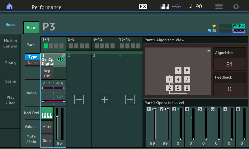
This single PART Performance contains an FM-X Part made from just two Operators. Just as in the previous example, Operator 1 (99) is the Modulator and Operator 2 (99) is the Carrier. Above, we have touched “View” to see the information split screen, and we have pressed the [PART – ELEMENT/OPERATOR] button to select the “Element/Operator” view.
You can see that Faders 1 and 2 are still up full in a similar manner to the previous example.
This time when you lower Fader 1, you hear that Operator 2 is no longer just a smooth, pure tone (Sine wave) as in P4. This time OP2 has a more complex timbre all by itself, and as you raise Fader 1 you can hear the timbre (tone) change further. We know now that by altering the Spectral FORM and SKIRT we can generate a complex source Wave from just a single Operator.
If you lower Fader 2, you hear nothing. The Modulator cannot be heard by itself. You can see that Operator 1 is, again, set to Feedback on itself.
In the screenshot below, PART 1 is selected (cursor highlights the Part 1 TYPE/NAME box) so that we can view the 8 Assign Knobs for PART 1:
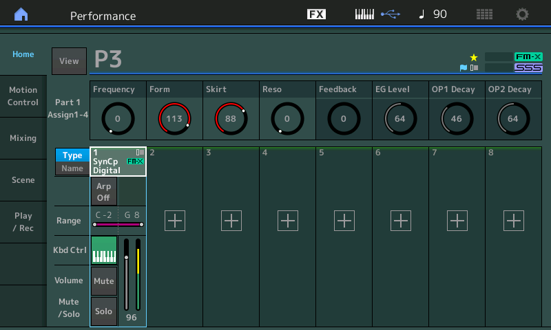
Compare the setting on our 8 PART Assign Knob parameters – these are what make the difference between these two Performance PARTS, P4 from last time and now P3.
The parameters have been given Names so you can see and experiment with changing this sound in real time.
Assign Knob 1: Frequency (OP Freq)
In the previous experiments we determined that Operator 1 (the Modulator’s) Frequency has been assigned to Assign Knob 1. Let’s learn about where and how this takes place. To do so let’s navigate to where Controllers are assigned to destination parameters. There are two methods to get there listed below – Learn to use both so that you can add to your navigation skills.
From the HOME screen you can manually navigate to the Control Assign area as follows:
- Press [EDIT].
- Make sure “Common” is selected in the lower left portion of the screen.
- Touch “Mod/Control” > “Control Assign”.
Alternatively, from the HOME screen you can take the following shortcut:
- Press [SHIFT] + [HOME] (INFO).
- From the “Overview” screen set the PART = “PART 1”.
- Touch the box “Part 1 Control Settings”.
We want to see the setting assigned to PART 1’s Assign Knob 1.
Touch the “Auto Select” box so it turns green (active).
Move Assign Knob 1 (this will automatically select its setup screen):
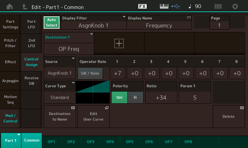
What you can learn from this screen is that physical controller (called the “SOURCE”) is “AsgnKnob 1”.
Locate the SOURCE box – this is where you assign/select the Control. The parameter (or “DESTINATION 1”) is “OP Freq”, Operator Frequency.
The “Curve Type” (Standard) and “Polarity” (Uni), you can see the graph (looks like a ramp) that increasing the Knob will increase the frequency. You can see that the OPERATOR RATE is being applied to only Operator 1 (value = +7).
Translation: The graphic next to CURVE TYPE represents what happens when the Knob is increased. You read it from left-to-right. You can understand this to mean: as the Assign Knob 1 is increased from minimum toward maximum, the Frequency of this Operator will increase. The amount that it will increase will be determined by the Operator Rate. You will notice that each of the 8 FM-X Operators could be included, or not, in this change – by setting an amount under the “Switch/Rate” for each Operator 1-8. Well, we are only using two (OP1 and OP2) so by placing a value next to Operator 1, we can conclude that turning this Knob will increase the Frequency of the Modulator at the Rate as set by the value shown – which is exactly what we concluded (by ear) in our first experiment. This screen is exactly *where* this change in Frequency is assigned to happen.
See the +7 value for OP1 Rate, change it to hear and understand that it is the “depth” control or the amount of application of Frequency change of Operator 1. Try all values from +7 ~ 0 ~ -7, while tapping on notes. Make a setting for this value, then turn Assign Knob 1. Hear and understand how the frequency change can be reversed at the parameter assignment (and not just by changing the direction of the Assign Knob). In other words, experiment at all values. Observe that when Operator Rate = -7 you can hear how increasing the Assign Knob does the opposite of the +7 setting, it lowers the frequency of the harmonics – even though the Ratio is positive with a Standard Curve. This is very much akin to closing a filter in an analog (subtractive) environment. Hear how it darkens the tone (timbre). It could be described as “placing a blanket over the sound”, “removing air from the sound”, “rounding the sound down”, etc., etc.
Experiment by changing the Ratio parameter from positive to negative to hear and understand how controllers are applied. When Operator Rate is +7 but Ratio is set to a negative value, you have reversed the movement. The graphic changes to illustrate what you are hearing.
Finally, change the Param 1 (Parameter 1) to see and hear how it influences the application of the Assign Knob 1. You will discover that “Param 1 = 5” is very much a linear application of the control, while a setting of “10” would apply the change very late in the movement of the knob. You have to move, see and hear this change for the concept to be clear.
Return the sound to “start point” settings.
Assign Knob 2: Form (Spectral Form)
Spectral Form allows you to select from six ‘other’ waveforms, other than the basic Sine wave and to construct other starting points. The setting of FORM = 113 will result in selecting one of the two Resonant Waveforms, “RES 1”. “RES 1” is described as being ‘broad’ (wide). In our previous article, we took a close up look at the parameter Assign Knob 2 is assigned to change. And we discovered that when the Skirt was unfurled a bit, we could recognize distinct differences in the “1” and “2” families of waveforms:
Simply touch Assign Knob 2, and because the “Auto Select” function is active (green) MODX will recall the Source/Destination assignment for this physical controller. Remember: Assign Knob 2 is changing the Spectral Form of the Carrier, Operator 2. As the Knob is increased the parameter is set to increase the value. The values between 98-117 are equivalent to selecting “RES 1”.
You can hear a distinct change in the character of the sound – and it is rather abrupt change at the change point. You should hear distinctly the 7 different tonal families depending on the position of Knob 2.
Assign Knob 3: Skirt (Spectral Skirt)
Skirt – all the SPECTRAL FORMS have a ‘skirt’ (except for the Sine). The wider the skirt, the more harmonics are heard; and the narrower the skirt, the fewer additional harmonics will be heard. Turning the Knob assigned to “Skirt” while Form is Sine (“Form” is a value between 0-19) – will result in no change in timbre. However, turning the Knob on any of the other six Forms will have a dramatic effect.
Our PART “P3”, starts with Form = “Res 1”; try moving the Assign Knob 3 through its range, listen for the change in timbre as you do; then set Assign Knob 2 to max (127) “Res 2” and try the same thing with Assign Knob 3. Notice an even more dramatic change:
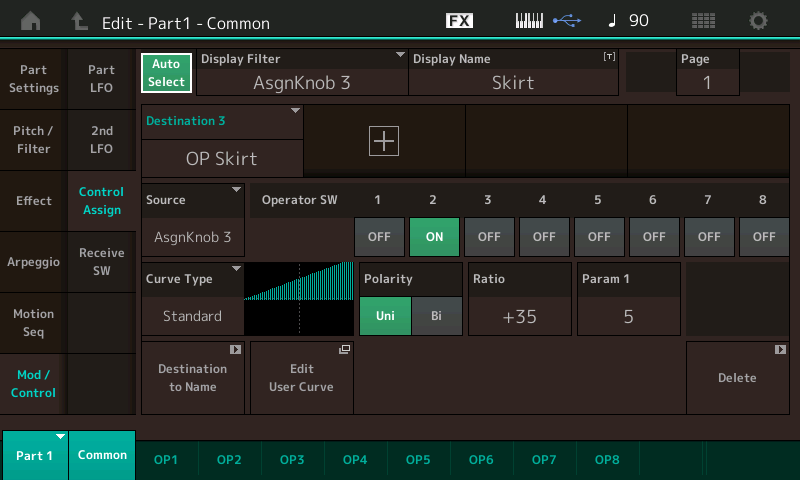
Simply touch Assign Knob 3 to view the assignment screen. As you increase the Assign Knob 3 you are setting the waveform to allow more harmonics. The screen tells us that we are adjusting the Skirt for OP2, the Carrier.
Assign Knob 4: Resonance
We learned previously that the Resonance parameter will be effective on the “RES 1” and “RES 2” Forms. Turning the Assign Knob 4 with the initial settings of Performance P3 will have a dramatic effect on the resulting sound. We know that the FORM (113) is RES 1 territory, so we can anticipate that increasing Resonance will rocket the harmonics skyward.
Note: If you need to return to the original Performance – you can simply click on RECALL in MODX Connect and then the top icon showing the direction “COMPUTER > SYNTH”; This will resend the program to the Edit Buffer again – restoring it to original condition.
Touch Assign Knob 4 to view the assignment screen:
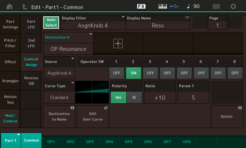
Here the Operator Switch is turned on for OP2 which we know is the Carrier. So the Resonance movement should, indeed, be dramatic – even though the Ratio is only set to just +10. As you can hear as you move Assign Knob 4, a little goes a long way! Notice with a good ear you can “tune” (select) the harmonic that is sounding.
Note: Press the [ASSIGN] button to toggle to control KNOBS 5-8 (flashes).
Assign Knob 5: Feedback
Feedback is the output of a source Operator being fed back to the input, creating a buildup in energy and in this case, since it is a Modulator being fed back on itself, expect a very subtle change in timbre. View the assignment by turning Assign Knob 5.
Assign Knob 6: EG LEVEL (Envelope Generator Level offset)
This is Envelope Generator Level and when we navigate to Knob 6, we discover that the parameter is “OP AEG Offset”, and is being applied to the Modulator (OP1); Value = +7.
Turning the Knob clockwise will increase; turning the Knob counterclockwise will decrease the Level of the Amplitude Envelope for timbre change. The more you raise Knob 6 the more you increase the influence of the Modulator. If you wanted to create an artful noise, a “spit” or some kind of chaotic noise at the attack of a sound, you would raise the “EG Level” (Knob 6) and lower the “OP1 Decay” (Knob 7) to make it short/quick, you could dramatically change the timbre of that chaotic noise by increasing the Modulator Frequency (Knob 1):
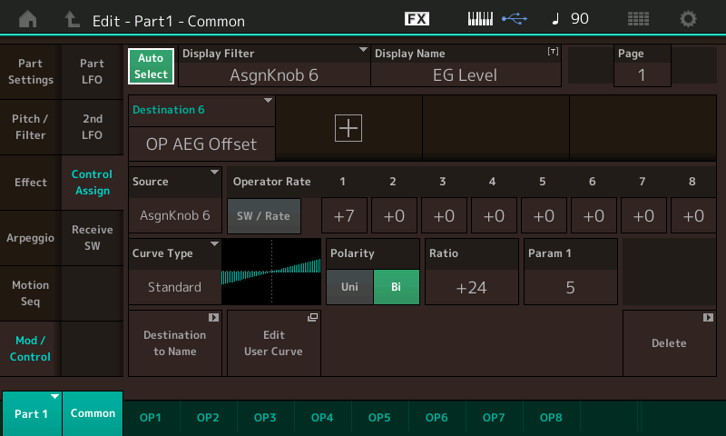
The Polarity being set to “Bi” means that the parameter can be both increased and decreased from its originally stored value. And with this Envelope Offset, this means we can lengthen or shorten the length of time that the Modulator has influence. In a future article we will take a close look at the Amplitude Envelope Generator (AEG) of an Operator. AEG is a fancy term for, how the sound starts, what it does while it is in and how it exits in reference to its loudness (Amplitude). It describes the loudness shape of the sound. Yes, here we are offsetting that AEG but we will ultimately want to know how to setup that envelope. For now, recognize that this OFFSET is being applied to or could be applied to each of the eight Operators with a differing amount of application.
Here we are simply offsetting the loudness envelope of the Modulator (OP1) so that we can easily make the timbre change component longer or shorter.
Assign Knob 7: OP1 Decay/Assign Knob 8: OP2 Decay
Turning them left and right you can hear that they affect the duration of the Modulator and Carrier, respectively. The Amplitude Envelope shape.
Turn Knob 7 to view the Control Assignment: We will look at the “Destination 7” first = “OP AEG Decay1” (we’ll come back and explain “OP AEG Release”, later):

Destination 7: “OP AEG Decay1” you see that Operator Switch #1 is active (green). The “Curve Type” is Standard, Polarity is Bipolar.
Translation: Turning this knob (Knob7) from 12 o’clock position will lengthen the envelope when turned clockwise and will shorten the envelope when turned counterclockwise. Decay determines whether the sound dies out immediately after the Attack portion. Does the sound remain at the same volume or does it diminish a bit while the key is held? Organ envelopes do not have any DECAY – they remain at the full volume all the time the key is held. A Piano envelope, by contrast, dies down a bit after the Attack portion and slowly dies out as time continues, so do all hammered, plucked or struck instruments. This behavior is considered “percussive”. The Decay setting determines if the sound dies out (or not) while a Key is held. This parameter is being applied to the Operator responsible for timbre change. The 12 o’clock position (64) represents the stored Amplitude Envelope Generator setting.
Assign Knob 8: OP2 Decay
Turn Knob 8 to view the Control Assignment:
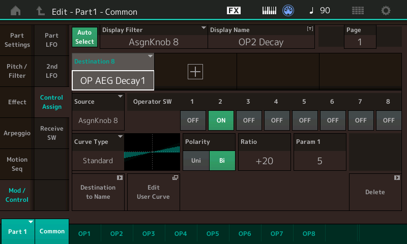
Turning this knob from the 12 o’clock position will length the envelope and turning counterclockwise will shorten the envelope, but this time you are applying it to Operator 2 (the Carrier). Destination 8 “OP AEG Decay1”.
Translation: The difference between the Decay of the Modulator and the Decay of the Carrier is something best understood by using your ears. The Carrier will affect the overall output level, the Modulator will affect timbre change in the overall sound. So when the Modulator has a longer envelope than the Carrier it is modifying, its influence will last throughout the duration of the sound, when the Modulator’s envelope is shorter than the Carriers then its influence will be momentary.
Let’s now return to Assign Knob 7 and view the other parameter that is assigned to change when Knob 7 is moved:
We’ve moved the CURSOR highlight to show Destination 9: ”OP AEG Release”.
Note: It may not be immediately clear but, this control matrix is huge. Each Destination has its own settings for Curve Type, Polarity, Ratio, Parameter adjustment, etc. and there can be 16 Destination per PART! So, the Curve Type and setting for this Destination can be different entirely from what we have setup for “OP AEG DECAY 1” in Destination 7 which also happens to be under control of the same Assign Knob. So, this one Knob is performing two different functions at two separate Destinations – each with its own response setting:
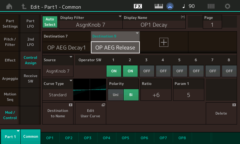
Notice it is assigned to affect both the Modulator and the Carrier: OP1 and OP2 Switches are active. “Curve Type” is Standard, the Polarity is “Bi”. Again, the Ratio of +6 means this is a very limited adjustment – it is controlling Amplitude Envelope Generator RELEASE.
Translation: what happens to the sound AFTER the key is released. So, a little dab will do ya’!
If you want the sound to ring out after you release the keys you can increase the RATIO in a positive direction.
Translation: This is using Polarity = Bi. Moving the Knob from 12 o’clock clockwise will lengthen the Release time of both the Modulator and the Carrier, turning the Knob counterclockwise will shorten the Release Time. Release Time is the parameter that affects what happens when you let go of the KEY or the SUSTAIN PEDAL. It is how long it takes the sound to die out. As you can see by the Ratio setting – the Release amount is very subtle. It is not going to last for very long even when turned fully clockwise. Increasing the RATIO will impact the total length of time the sound lasts when the key is released. Between Knobs 7 and 8 you can create all kinds of envelope shapes for the sound. Notice how DECAY is different from RELEASE.
“Decay” occurs during the key being held, “Release” only occurs when the key is let go. If the Carrier Decay is very short, there may be nothing left to sound, even if the Carrier Release is set long.
TIME, LEVEL and Building FM-X Amplitude Envelopes
When you strike a Key, the behavior of the sound in terms of its loudness is described by its Amplitude Envelope Generator (AEG). In analog synthesis, this was called the ADSR (Attack, Decay, Sustain, Release) – and in general, this describes how the sound comes in out of the silence, if it is a percussive sound there will be a peak of loudness made by the Attack, it will drop off in level (Decay), and if it can be held, it will sustain, until the Key is released. But ADSR on four sliders is only one way to describe AEG. In the FM-X engine, you have a series of TIME and LEVEL parameters that define this shape:
- TIME is simply “how long” it takes to get somewhere.
- LEVEL is simply “how loud” it is at that point.
The higher the TIME value, the longer it takes to get there.
The higher the LEVEL value, the more intense the amplitude is at that point.
- Press EDIT
- Select PART 1
- Touch “OP2”
- Touch “Level”
- Highlight TIME parameter “DECAY 1”:
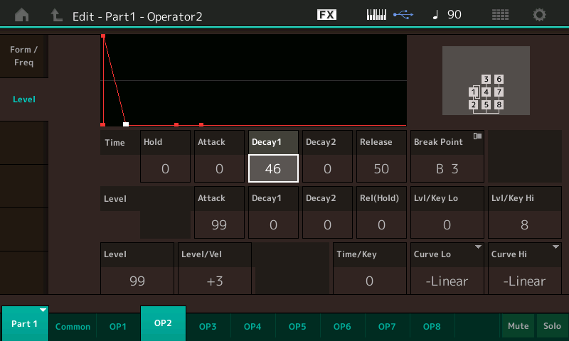
We experimented with Assign Knob 8 set to control OP2 Decay. Here is where that particular parameter lives. Working with OP2 (Carrier) above, you will quickly understand how shortening and lengthening the Decay works.
Highlight TIME parameter DECAY 1 (46) as shown above: Move this to a lower value (see and hear). Then move this to a higher value. Time parameter DECAY 1 will impact what happens if you strike a key and hold it down. Lower values the sound will reach a LEVEL of 0 in spite of you holding the key – but as the values increase, you can get a longer envelope shape while the key is held, which means more time before LEVEL of 0 is reached.
Now this is important. When you change this parameter directly (Decay1), you can set it to 0 through 99 – getting the full range of the parameter. When we moved Assign Knob 8 (OP2 Decay) we were only moving through a specifically limited range of values (set by ear) and set by the RATIO setting. When you view the “OP2 DECAY” Assignment – it is Bipolar (which means we are using the Assign Knob to move above and below the stored value. The “stored” value here is “46”. So, when we move the Assign Knob 8 from its 12 o’clock stored position, we can shorten and lengthen the duration of the sound – but notice the range is restricted by the Ratio setting. The RATIO setting being +20 limits the range of change. The larger the RATIO the bigger the range for the assigned knob to move above and below that stored setting.
If the Polarity was Uni this would mean we can move from the stored value but in one direction and back.
Experiment with what you see and hear. Hint: the values are not a linear scale. They are designed and optimized for musical use, so the weighting of the time is concentrated in the short time area.
TIME
- HOLD – the amount of time before the envelope begins, the time between Key-On and the Attack. You can delay the start of the envelope by putting a value here. (Careful, HOLD = 99 can be over a minute and half) Hint: Do not worry about the time. In seconds – set these envelopes by ear!
- ATTACK – the amount of time between envelope start and the full Attack Level.
- DECAY 1 – the initial decay in the sound. The Time it takes to reach Decay 1 Level.
- DECAY 2 – the secondary decay in sound. The Time it takes to reach Decay 2 Level. If Decay 2 Level is 0 the sound will die out no matter you are holding down the keys (like a piano or any percussion instrument) If DECAY 2 Level is 0 the vibration of the instrument stops. If Decay 2 Level is a value other than 0 the AEG will eventually settle at that Level until you let go of the key. If you release the KEY prior to the TIME outlined by your AEG settings, the RELEASE parameter setting takes over. If you continue to hold down the key the sound will remain at DECAY 2 LEVEL indefinitely.
Experiment. In our next installment, we will look at two more Performances – each built, again, with just two Operators in the same Modulator:Carrier arrangement. But we’ll build an entirely different set of tones. In PERFORMANCES P4 and P3, the basic tuning of the OPERATORS was 2:1 – meaning that when a key is struck say A-440 – the Carrier outputs 440Hz, the Modulator outputs 880Hz (that is your 2:1 ratio). In the next installment we will look at two PERFORMANCE where the Modulator to Carrier Ratio is 1:1. The result will be an entirely different set of timbres. Until next time!
Join the discussion about this lesson on the Forum here.
Haven’t had a chance to check out Part 1 of the series? Catch it here.
Ready for next lesson? Part 3 is now available here.
