Mastering MODX: Super Knob Complex
PERFORMANCE: Super Knob Complex
(This Performance example is found in the tutorial content file “SuperKnobExamples.X8U“)
This type of Performance is very useful for typical EDM Synth Chord Sequences. The Super Knob modulation works from percussive sequence sound (left) to full chord sound (center) and continues with filter control from center to right. (Please note: The Live Set that is used in the Mastering MODX series is located here).
It is an example for dividing the ranges of Super Knob movement into “left-to-center” and “center-to-right” for two different modulations. Compared to the previous examples, this Super Knob programming is already more complex and multi-dimensional.
This will require routing the corresponding Part Assignable Knobs to the Common Assignable Knobs on the “Edit-Common/Audio” level. And then assigning the PART Knobs to the controlled Part destination parameters.
Let’s decipher what Knobs are assigned to the Super Knob.
Navigation tip: By looking at the OVERVIEW screen we can learn that PART 1: AssignKnob1, AssignKnob2 and AssignKnob3 are under control of the Super Knob.
From HOME: Touch “Motion Control” > “Overview”
or
From HOME: Press [SHIFT] + [PERFORMANCE (HOME)]
The cursor highlights the “PART” or shows “COMMON” – you can select to view any of the overall controller assignments or just a single Part’s controller Assignments.
Set PART = “Part 1”
View PART 1 (I have removed the “FADER” connection from the view to isolate the Knobs):

We also learn, by selecting “PART 2” that PART 2’s: AssignKnob4 and AssignKnob5 are under control of the Super Knob:

On the MODX in order to view Knobs 5-8, simply press the lit [ASSIGN] button (it flashes when 5-8 are selected) this toggles the view between Assign Knobs 1-4 and 5-8:

The Overview is one way to see this – the actual Controller assignment takes place on the “Edit – Common/Audio” > “Control” > “Control Assign” screen.
Below we have set the DISPLAY FILTER to “Super Knob. Four Destinations of the sixteen available for this level of Editing are shown at a time:

PAGE 2: To see the next four Source/Destination locations, advance the PAGE to PAGE 2 (shown below):

The five Destinations are as follows:
Part 1 Assign 1
Part 1 Assign 2
Part 1 Assign 3
Part 2 Assign 4
Part 2 Assign 5
Now, in turn, move each Assign Knob 1-5, directly – each Assign Knob’s Destination is shown individually. As you can see the Part Assignable Knobs are all assigned to a corresponding Common Assignable Knobs. This allows individual control of each assigned parameter.
Because the “AUTO SELECT” function is active (green) moving any controller will reveal what is assigned to that particular device Additionally, utilizing the “Auto Select” feature, you can turn the Super Knob and review just those controller assignments linked to its movement. Because these assignments are basically made as you develop your ideas about what you want to accomplish, you will naturally start by assigning individual controls to a knob, but recognize that it can get as complex as you desire. Multiple destinations can be assigned to a single knob. This is important to mention here because often you may be using two similar PARTS to create a LEFT and a RIGHT version – and will want to use a single Knob to control both together. We’ll get to that in a future article… but it is important to mention that you have the choice! (For now we’ll keep it so each is assigned a separate Knob).
To locate what is shown above in the actual MODX, from the PERFORMANCE (HOME) screen:
- Press [EDIT] (Edit – Common/Audio)
- Select “CONTROL” in the left column in the screen
- Select “CONTROL ASSIGN” in the second column
- Activate AUTO SELECT and turn the first 5 Knobs.
Common Assign Knob 1/ Part 1 Assign 1. This is on that upper level COMMON/Audio – the overall COMMON Level. The actual PART 1 Assign 1 DESTINATION parameter is “Volume”
Part 1 of this example includes a percussive analog synth sound, which is faded out (volume) by moving the Super Knob to right (Destination 1). At same time the Filter Decay Envelope gets longer (FEG Decay1 – Destination 2) and the Reverb Send increases (Destination 3).
Highlight each of the DESTINATIONs 1, 2 and 3 in turn to view the SOURCE, CURVE TYPE, POLARITY, RATIO and PARAM 1 (curve dynamic) for each assignment.
Navigate to PART 1 – you can do so by highlighting the “Destination 1” box since it is assigned to control PART 1, the “Edit Part 1 Control Settings” shortcut appears touch that to be whisked directly to the PART 1 Controller Sets…
Below: See the three PART1 assignment Destinations simultaneously, by touching the Super Knob; recalling setting the DISPLAY FILTER = SUPER KNOB:

Above Translation: Turning the SUPER KNOB will recall the Destination parameters of PART 1 that will be affected by its movement. They are: 1 (Volume), 2 (FEG Decay1) and 3 (Rev Send). Currently Destination 1 is selected and we can see that Volume is linked via AsgnKnob 1. Therefore, as the Super Knob moves Assign Knob 1, the volume of PART 1 will follow the CURVE as shown. It is a negative RATIO so the Volume will be turned down. The Volume is not reduced until way late in the movement of the Knob.
As you highlight each Destination, in turn, you can see what SOURCE (which physical Assign Knob) is directly involved. Each Destination will have its own programmable Curve, Polarity, Ratio, etc.
As you turn AsgnKnob1 towards maximum you will hear the sound rapidly drop off after you reach about 4 o’clock.
As you turn AsgnKnob2 towards maximum you will hear the filter envelope get longer and longer – allowing more sound output and a brighter tone.
As you turn AsgnKnob 3 toward maximum you will hear an increase in the Reverb.
As you turn the Super Knob all of these happen simultaneously with a single gesture. And, importantly, each can be scaled to perform as you design.
Hint: You can [SOLO] PART 1 or simply [MUTE] PART 2. By isolating just PART 1 you can hear how turning ASSIGN KNOB 1 turns down PART 1. Notice the RATIO is -32 (Negative values reduce), and the PARAM 1 function (10) is the CURVE you are hearing – changing this to anything else will make this clear. Please experiment. When PARAM 1 = 0, notice that the turn-down in volume is practically immediate. PARAM 1 = 5 is basically linear
Since five of the SUPER KNOB functions are listed in the upper COMMON level – three to PART 1 and the last two (KN4/KN5) that are affecting PART 2. These are seen by selecting PART 2 and viewing its individual PART CONTROL > CONTROL ASSIGN
Part 2 includes a fat, stacked trance pad sound, which is faded in moving the Super Knob to right. Starting from the center position the filter modulation starts.

PART 2 – DESTINATION 2 Cutoff (Assign Knob 5) – as you turn the Super Knob clockwise you close the FILTER for all Elements.

SELECT PART 2: Nothing is assigned to PART 2 for Knobs 1, 2 and 3 – But KNOBS 4 and 5 are set to VOLUME and CUTOFF.
You can isolate PART 2 and listen to how individual Knobs 4 and 5 interact with PART 2.
Notice that in the screen (Destination Volume) this is COMMON VOLUME and affects all Elements. While the Destination 2 on the right (Cutoff) is a destination that can be switched per Element (similar to the Motif Control Sets).
Explanation: The Common VOLUME parameter turns all Elements in this PART up or down together, if you wish to control individual Elements you would target “Element Level” not the Common Volume. Since each Element has its own FILTER and therefore its own CUTOFF setting, you can opt out or opt in on a per Element basis when you are dealing with this setting. The MODX will show you the Element Switches based on the DESTINATION parameter in question.
If you have any questions or comments about this article, please join us to discuss them on the Forum here.
Catch up on the previous article in the series – “Mastering MODX: Super Knob Morph” here.
Next article: “Mastering MODX: Super Knob Values“.


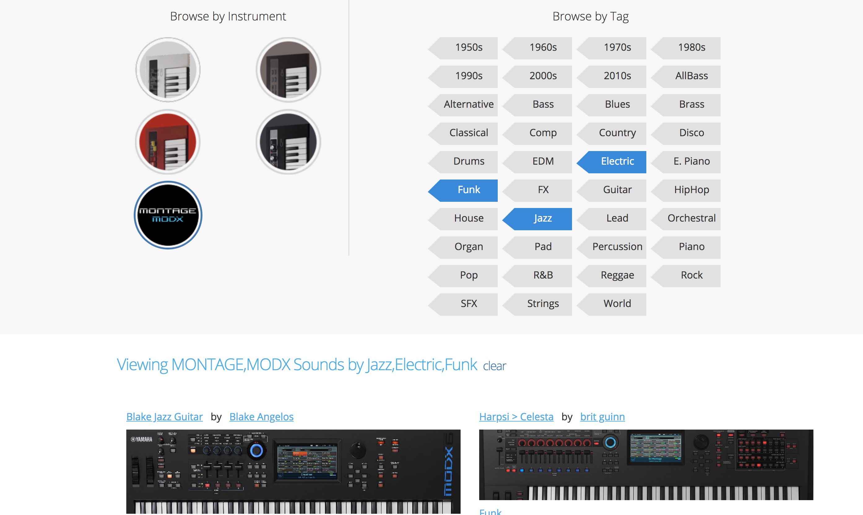
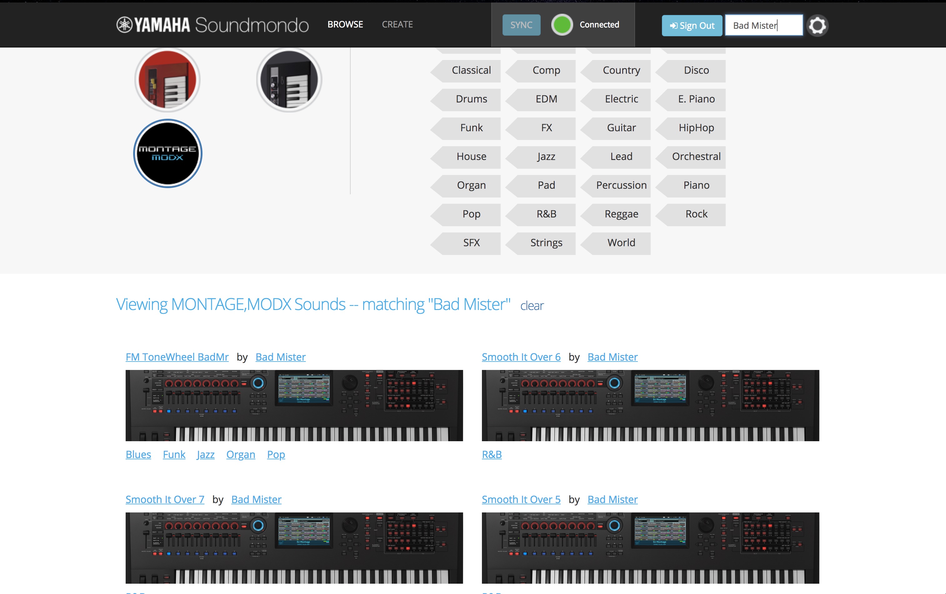
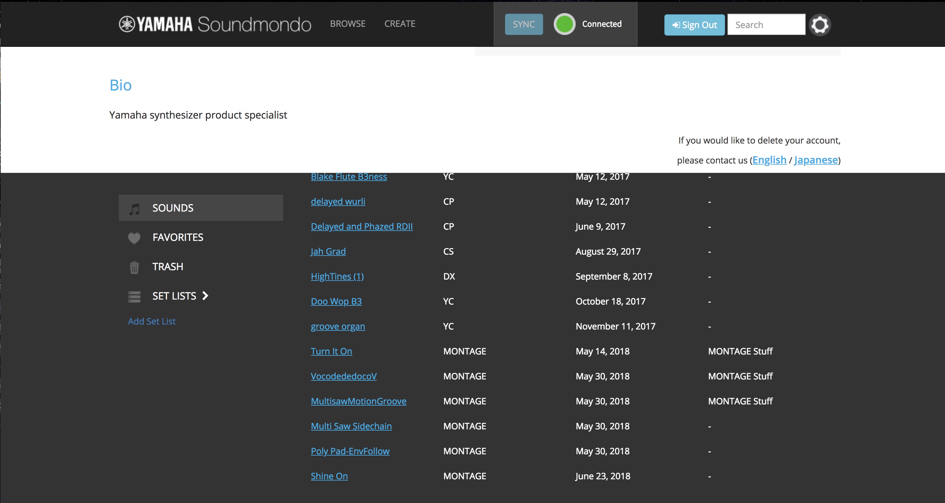
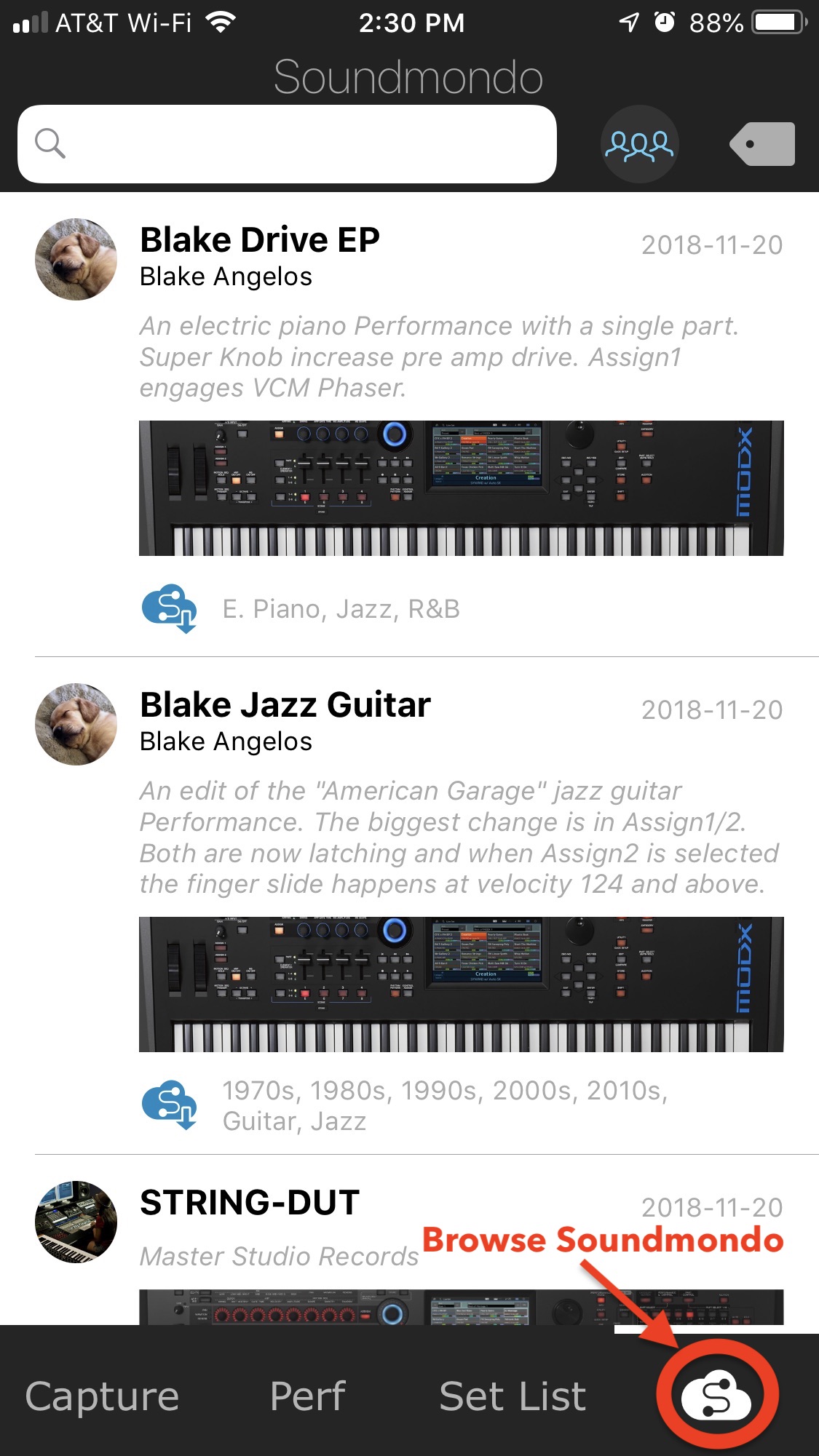
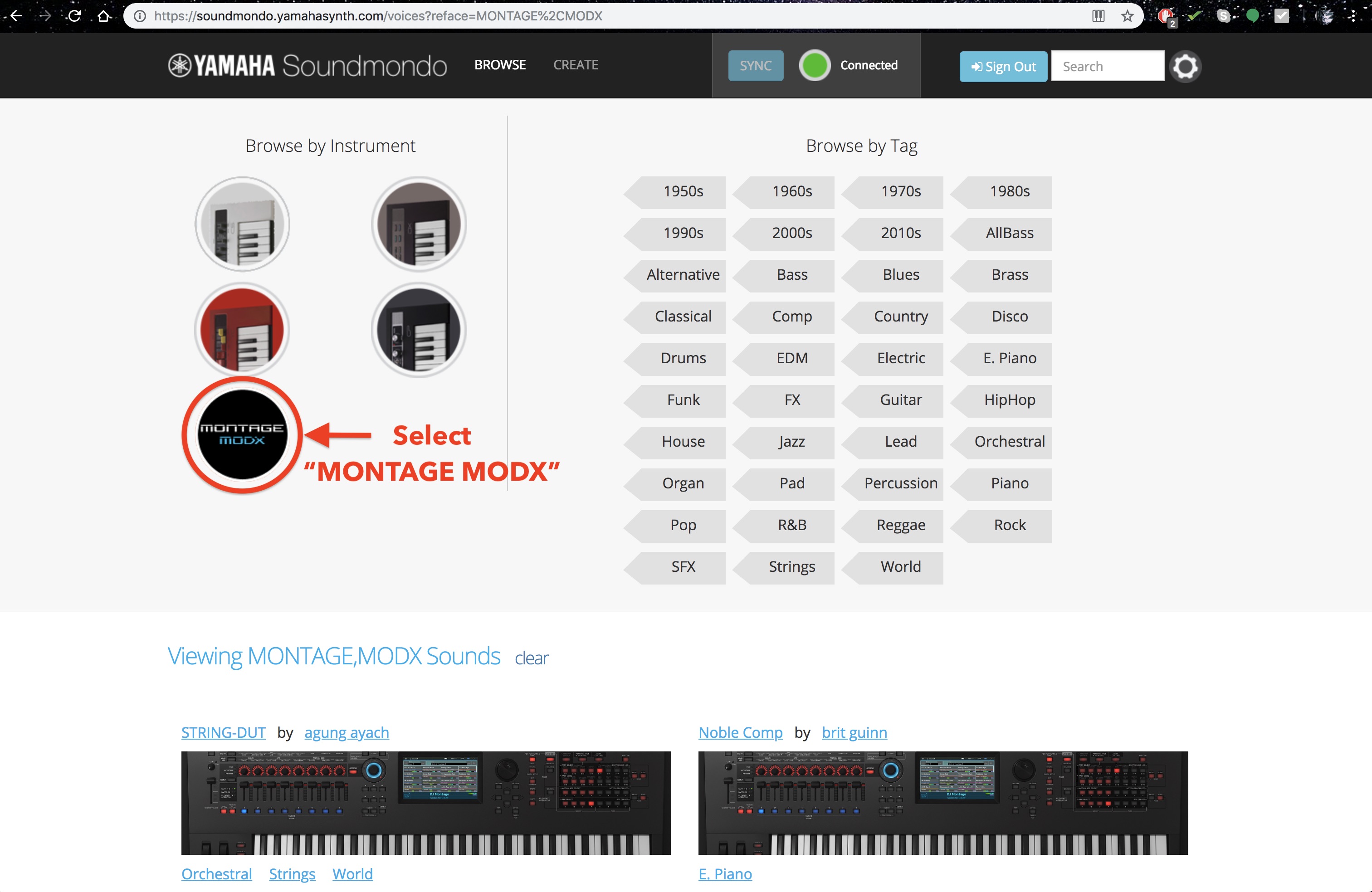 In the screen below, I have searched using the tags. Below are some Performances returned for the tags “Funk”, “Jazz” and “Electric”. To clear the result, click on “clear” in the screen:
