Understanding Signal Flow of VST Routing
When working with your synthesizer and computer DAW recording MIDI, you most often will work with LOCAL CONTROL = OFF. We will start our discussion with the KEYBOARD (controller). This includes the keys, the wheels, the pedals, the knobs, the sliders, the buttons, the ribbon, etc., etc. In its role as ‘controller’ it will generate MIDI messages that will travel through the USB or FW cable to the computer. In a normal play situation (without the computer), the controller triggers the synthesizer tone engine directly and all that MIDI message stuff is unnecessary. But in a computer setup we want to send the coded MIDI messages to our DAW first. They arrive at a MIDI Track created to receive IN the messages, document them to a track, and echo (also called “thru”) them back OUT to a tone generator. The TONE GENERATOR is responsible for generating AUDIO. You can then choose to send the audio to the speakers or back to the DAW.
What we want to discuss right now is that the EDITOR VST is situated between the TRACK’s MIDI OUT and the hardware synthesizer itself. You press a key on the keyboard, its message is routed OUT via USB/FW to the computer. Cubase is set to receive (in) MIDI INPUTS.
We will use the Motif XF7 connected to a computer via FireWire for MIDI and AUDIO as our first example.
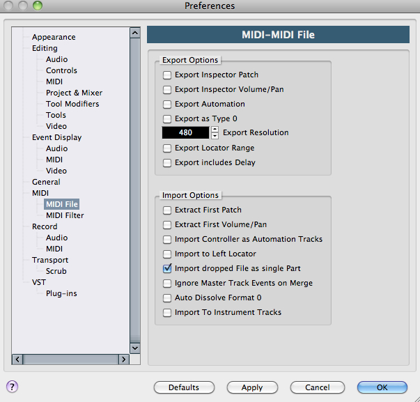
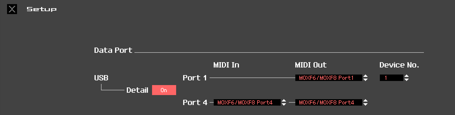
The CUBASE MIDI parameter is set here:
DEVICES > DEVICE SETUP… MIDI > MIDI PORT SETUP (shown below how it looks on a Macintosh Computer)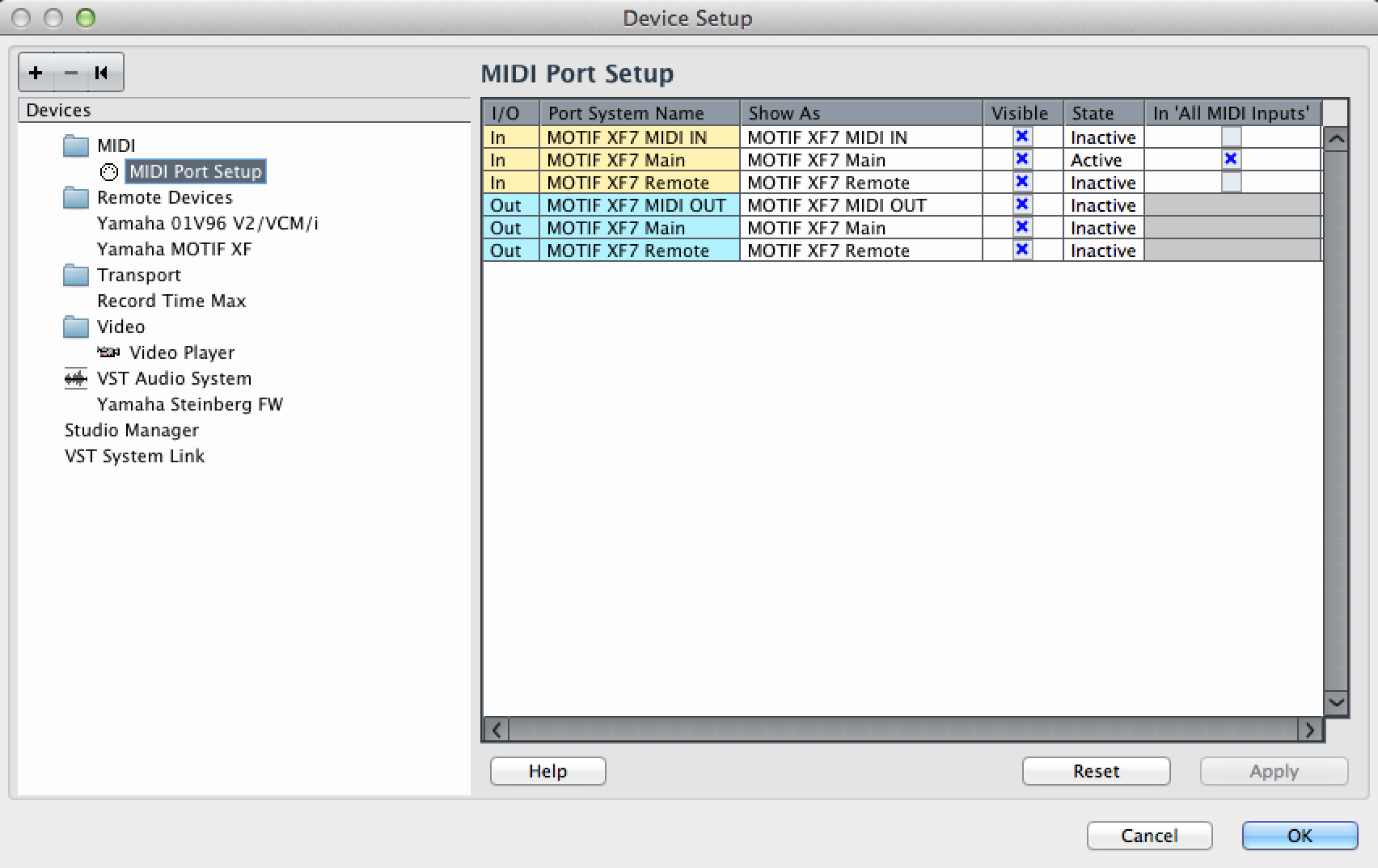
Coded messages from the KEYBOARD are received in the computer. Notice the column labeled: “In ‘ALL MIDI INPUTS'”. In this column you will mark all devices that you wish to be sources for MIDI data recorded to Cubase MIDI Tracks. You will notice that the “Motif XF7 Main” is marked as the input source for MIDI Tracks. This parameter is immediately impacting the MIDI Track Inspector’s MIDI IN. (We should mention that in the situation where you wish to use a second MIDI controller connected to the Motif XF, you can. You would additionally mark the PORT that this external device is connected to… Shown below, as it would appear on a Windows computer, is the “Motif XF7 MIDI IN” marked – indicating that second controller will be able to trigger whatever you select for the MIDI Track’s MIDI OUT setting. That is, both the Motif XF keys and the keys of the external device connected to the XF’s 5-pin MIDI IN jack will be considered INPUT DEVICES for MIDI when you set the Track’s MIDI IN = ALL MIDI INPUTS.
(Shown below as it would appear on a Windows computer).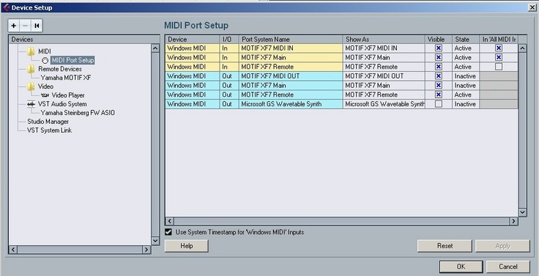
In this all important column (In ‘All MIDI Inputs’), which defines what is your musical data input device(s), the Motif XF REMOTE should NOT be selected. Remote DAW Control messages must be kept discreet – on their own dedicated PORT – and never mixed in with your musical performance (track) data. In the left pane you’ll find the REMOTE DEVICES folder, which contains the “Motif XF Remote” setting for bi-directional communication between the DAW REMOTE layer of the XF and Cubase.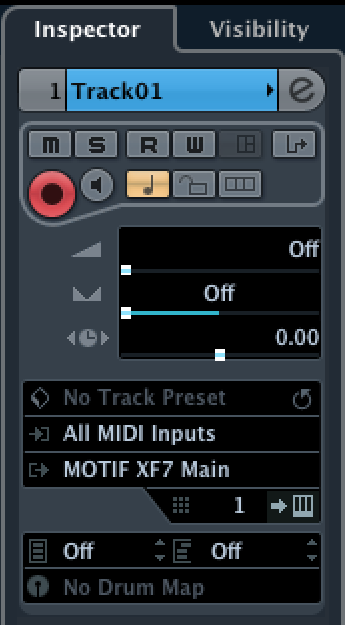
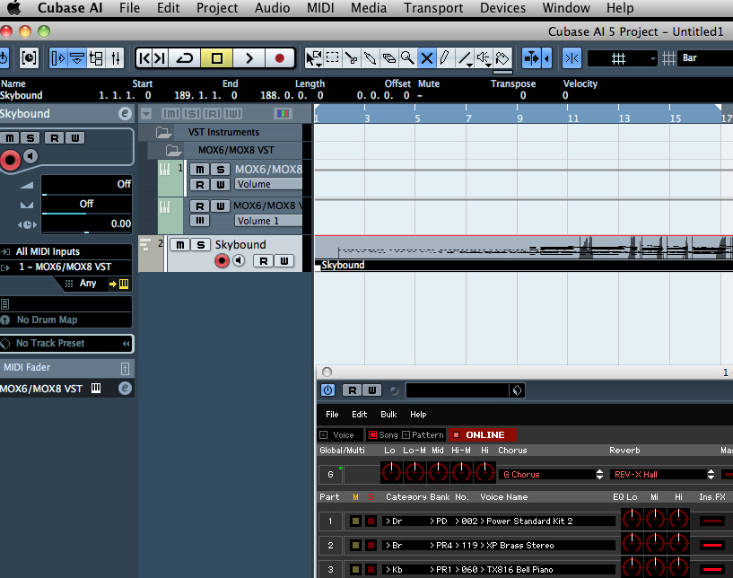
Shown at left you see the Cubase (TRACK INSPECTOR) MIDI IN is set to “ALL MIDI Inputs”. You can understand now how this allows you to define multiple MIDI controllers simultaneously (their data is merged by this selection) and use the active MIDI Track to “THRU” (echo) the data to a particular MIDI device on a particular MIDI CHANNEL to the selected OUT device. When you select (highlight) a MIDI Track in Cubase, this is what determines which device responds to the MIDI messages. Because the LOCAL CONTROL on your source keyboards are set to OFF, and because the “Motif XF Main” is set as a MIDI INPUT Source, and because the “Motif XF Main” is set as the MIDI OUT, and because CH is set to 1 – you know that the sound will be coming from the PART (or PARTS) set to receive MIDI Channel 1 in your XF7.
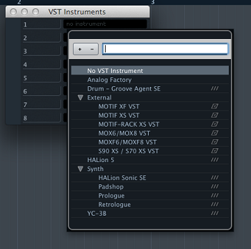
In the screen shot initially the MIDI OUT is set to return to the “Motif XF7 Main” – which is the main Motif XF tone engine (hardware). We want to point out that this is different from the destination when you are using the “Motif XF Editor VST”. As we mentioned – we are going to route the MIDI OUT of the Track to the Motif XF EDITOR VST (software) and let it communicate with the hardware Motif XF. When launching the Motif XF VST (Devices > VST Instrument > External > Motif XF VST), the destination setting is critical. Let’s see how this works:
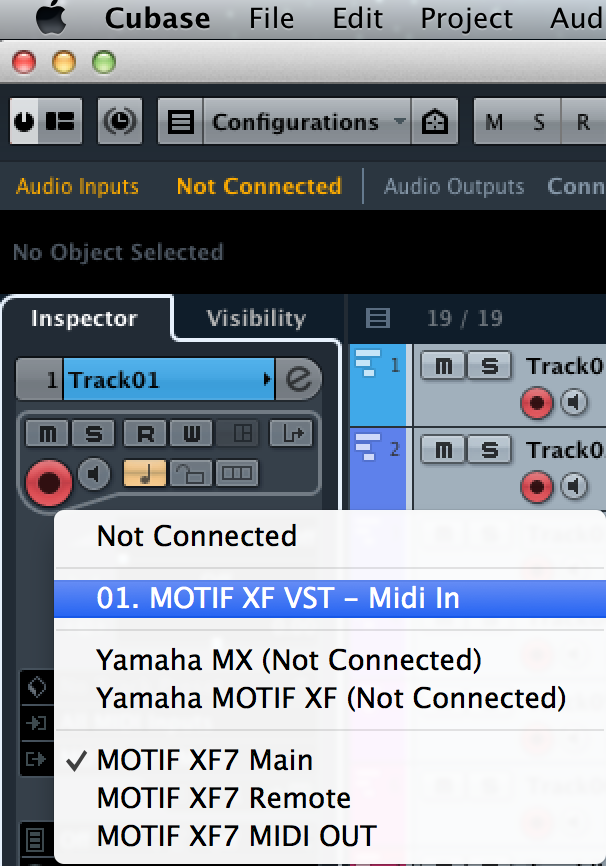
If you click on the MIDI OUT setting you will launch a window that allows you to select the “Motif XF VST-MIDI In” as the destination. Doing so will allow the data traversing this MIDI Track to travel to the Editor VST – you will see the graphic keyboard respond when MIDI events arrive from the currently selected Cubase track or when you play physically on the XF’s keybed. Changing the MIDI OUT of a track from “Motif XF Main” to “Motif XF VST-MIDI In” is significant and necessary to complete the VSTi routing setup.
When you click on the MIDI OUT line you will see a dialog box with multiple selection options.
There are multiple areas in this setup box:
NOT CONNECTED – use this setting when you do not want MIDI to be THRU’d to any tone generator. This would be used, for example, when creating a “dead-end” for arpeggio data generated in the source keyboard. This will be covered in a separate article. But there are actually times when you actually want to route a track to a “dead-end”!
01. MOTIF XF VST – Midi In – this second area is where your VST instruments (soft-synths or external VSTi’s) will appear. This is what you want to select for our particular example. The Number will indicate which instance of the Motif XF VST you are running. (Multiple instances of the Motif XF VST can be run when you use the Cubase “FREEZE” option). When the “Motif XF VST – MIDI In” option is selected the graphic keyboard in the Editor will respond to MIDI data that is being routed through/from the (selected) Track.
XML SCRIPTS – this third area will contain any XML Script (Voice Lists) that you may have installed or that maybe pre-installed. (If you have no XML Voice Lists installed you may not even see this division, however). In general, you will find using the Editor VST superior to using the XML because the Editor VST is easily updated to include customized and User Voice locations. In addition to being able to edit every Voice you are using, the VST Editor also has access to the unlimited Voice Library via the Cubase MediaBay: Sound Browser. XML scripts are only as good as the last time someone updated them – which means if you are using USER Voices, the list is already out-of-date. With XML the Voice Lists are limited to just the Voices physically contained in the hardware – while the Sound Browser can give you quick access to every Voice you own – whether currently loaded in the synthesizer or not. (We should also mention, if you are so “old-school” you cannot live without your XML file, you will still want to keep the EDITOR VST running in the background – as while it is ONLINE it will backup everything, automatically, anyway.
The next region (at the bottom) contains the MIDI Device driver options. This would be where you normally connect, when not using the VST routing or the XML Voice List option.
Very Important: When you launch the VST Editor inside of Cubase it will automatically make the “Motif XF VST – MIDI IN” assignment when it creates your first MIDI Track. Create a new MIDI Track for each PART you wish to record and make sure it is assigned similarly to the “Motif XF VST’s MIDI In”. This is essential for MIDI data to be properly routed through the system. With the EDITOR VST lauched and the created MIDI Track selected, when you play the keys you will see the keyboard icon in the editor respond showing that MIDI messages have traveled from the XF Out via FW-MIDI into the computer and into Cubase. They arrive as an MIDI INPUT to a MIDI TRACK that THRU’s the data to the Motif XF Editor VST.
The Editor VST, when in proper communication with the Motif XF, establishes a 1:1 relationship. Bi-directional and simultaneous commuicaton exists when you have the Editor “ONLINE”. The MIDI messages can now trigger the Tone Generator of the Motif XF (the PARTS assigned to Channel 1, in our example).
What happens to the signal next is very important to understand. The MIDI messages have finally arrived at the synth tone engine, the synth outputs audio – you can route that audio either to the Main Left/Right analog Audio outputs of the XF (considered the “Direct Monitor Output” path) or you can route that audio (digitally) back to Cubase via FW – where it would be routed through the VST INSTRUMENT AUDIO Lane.
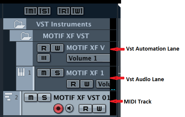
You monitor the XF via the Direct Monitor Output route in most cases – you typically would MUTE (“M”) the virtual Audio signal in the Audio Lane. You do not want to listen to both routings because the Direct signal is a few milliseconds in front of the Audio Lane (which has to be processed by the computer and is called the Latent signal). If you activate both you will hear “doubling” – and this is not what you want.
Doubling: This “audio doubling” what is it about, and why does it occur, and which one of the two signal paths should I be listening to?
This is an important series of frequently asked questions and is something that you should not guess about. It is something you should decide on and execute based on what you want to accomplish. Any audio interface will route signal to your speakers so you can hear (monitor) what you are doing. You have a rather unique situation with the Motif XF where your audio interface is built-into your synthesizer keyboard… and that keyboard has a signal path to your speakers all of its own. Make sense? (a standalone audio interface, typically makes no useful sounds, your XF does!!!) You normally listen to this direct audio pathway – because it is immediate and latency free. The signal, that travels to the computer must be timestamped and placed on your computer’s hard drive before it is “echoed” back to the audio interface to be heard in your speakers. Albeit just a few milliseconds, this can be critical in some instances. During the Record process – it’s a no-brainer about which one you will want to hear. You want the latency-free, direct signal. You will record the other (it is exactly the same signal) and you will check that everything is as it should be by listening closely to the PLAY BACK. That will be the very first time you hear the signal that was sent to the computer.
So when would you want to monitor the latent signal? When you are, in real time, processing this signal with a computer-based VST Effect. You will have to determine if this will work for you, musically.
If you are used to analog (tape) recording, you dealt with a similar situation when you were in the recording studio. The engineer put out a bunch of microphones and direct boxes for the various devices and those signals arrived at the studio’s mixing console – where the engineer prepared several signal paths… one was sent to the multi-track tape recorder maximized for RECORD level etc. A second mix was sent to the monitor speakers in the studio’s control room. The engineer would adjust the levels of the various inputs to create a more balanced mix of the entire ensemble. This second “monitor mix” was the subjective mix that traveled to the speakers, the other path (maximized record levels) is sent to the multi-track recorder. Not until PLAY BACK did the engineer know for sure what was recorded. You did not listen to (monitor) the tape signal initially – during the original record – you monitored the direct signal. The signal going to the multi-track recorder would magnetize particles on the tape and have to travel an inch or two to get to the Playback head (there is your latency) – yes even in the old days you dealt with the recording device introducing a latency into the signal path. Back in the day it was due to the physical distance that the taped signal had to travel from the RECORD HEAD to the PLAYBACK HEAD… now it is a matter of CPU speed in being able to accurately timestamp and then read and replay. But the solution is the same in both the analog world and today’s computer-based digital world… You may want to avoid being downwind of the Latency whenever possible. You can avoid this easily with external hardware by opting to monitor DIRECT. (There are times when monitoring the signal through the DAW is appropriate. The key to all of this is know what you want to hear, and how to select which path you are monitoring).
Thinking about it logically, it makes sense. You should learn to listen for this “doubling”. It should sound unnaturally big, and not “tight” – not focused. You can easily identify the difference by clicking on the “M” (MUTE button) on the Motif XF VST Audio Lane. This will defeat the Latent signal, and allow you to monitor yourself direct (as you would if no computer was involved).
Preventing Doubling: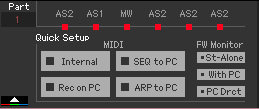 We will begin our discussion with an explanation of the QUICK SETUPS and FW MONITOR SETUP found in the lower left corner of the Editor VST. These make all the critical settings within the Motif XF for the different functions you may be performing.
Internal – Using the Motif XF without sequencing.
REC on PC – When recording Tracks to the DAW
SEQ to PC – When executing a real time MIDI transfer from the Motif XF sequencer to a Cubase MIDI Track.
ARP to REC – Specific use case for recording MIDI data from normal note oriented (sort/thru) arpeggios
The FW Monitor options determine how audio is routed
St-Alone – Audio travels from the XF directly to its main L/R Outputs
With PC – Audio is prevented from traveling direct to the main L/R Outputs, it travels to Cubase via VSTi routing to the VST Audio Lane
PC Drct – Audio routed to assignable FW outputs can be monitored direct while audio from the DAW is also sent to the main outputs. This should be selected when recording your keyboard performance to the DAW software on the computer. The audio signal of the MOTIF XF will be output directly via the main L/R OUTPUT with the audio signal sent from the DAW software via an IEEE1394 cable.
FW MONITOR SETUP = With PC
This should be selected when you are using the MOTIF XF as an audio device with the DAW software. When this is selected, the audio signal of the MOTIF XF will be output to the DAW software on a computer via an IEEE1394 cable, merged and mixed with the DAW sound, returned back to the MOTIF XF, then output via the OUTPUT L/MONO and R jacks. Selecting this allows you to apply VST Effects within the DAW software to the MOTIF XF sound.
The key here is, without this type of routing scenario, you would not be able to apply VST Effects to your MIDI Tracks. But by returning AUDIO via this special routing setup, instead of the XF audio going directly to the main L/R outputs (as would happen if there was no computer), it is sent via FW to the computer, where it can be processed (in the same fashion as any soft synth would) by VST Effect. The audio is then monitored through the AUDIO LANE and merged with other audio on the DAW and sent to the audio interface (your XF’s main L/R outputs).
FW MONITOR SETUP = PC Drct
This should be selected when you want to monitor what YOU are playing “live” (direct), yet you want to hear audio coming from the DAW. You are overdubbing to audio already recorded in your DAW, and/or you are routing what you are playing through a discreet assignable FW bus. Remember only the STEREO L&R Outputs are connected to speakers. When you route a PART to an assignable FW output, say FW1&2, it is removed from the main System flow… and therefore it would not be able to be heard at all. The “PC Drct” options allows you to monitor those PARTS you might assign to the FW1-FW14 (assignable) outputs by routing their audio directly to the main Stereo L&R output for monitoring purposes… (of course, the signal is documented in the DAW as well, but you only need to monitor it once). The PC Drct option prevents the dreaded “doubling”.
Troubleshooting the FW Routing sitution:
RULE: Follow the signal from source to destination. Like following water through a pipeline when looking for trouble, this rule will help you when trouble occurs.
Situation: You are recording MIDI data to Cubase (DAW) and using the Motif XF Editor VST. Your MIDI and Audio connections are being handled by the optional FW16E.
_ Key presses and controller movements will travel OUT via MIDI from the XF (because Local Control is OFF, they do not trigger the XF tone engine… so with Local Control OFF you should expect NOT to hear your XF making sounds).
_ You will know that MIDI is arriving in Cubase (DAW) because the selected (highlighted) MIDI Track has a single bar MIDI Activity meter that will respond when you press a key or wiggle a controller. The “ALL MIDI INPUTS” setting on the MIDI track will include your “Motif XF Main”.
_ The MIDI OUT of the selected track will be set to “thru” the signal to the “Motif XF VST – Midi In” (the Editor). You will know your message has gotten this far as the keyboard icon of the Editor will animate to show you what keys you are pressing.
_ With the Editor VST “ONLINE” it is in 1:1 communication with your Motif XF hardware. The Editor VST is the representative of the hardware XF in your computer environment.
_ If the Editor VST is showing activity (keyboard is responding by showing what notes are playing), and you are still not hearing sound, then you know that signal is this far and the problem is now down to AUDIO RETURNING.
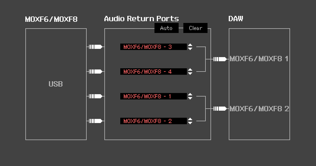
_ In the Editor VST, go to FILE > VSTi SETUP > and ensure that you have audio RETURNING from the Motif XF (left side of the screen) to DAW Cubase (right side). The XF’s available Outputs appear in the center column. Also ensure that there exists a path for the assigned OUTPUT SELECTION… Motif XF Main L and Motif XF Main R should be set as the first stereo pair of Returns.
_ Check the “FW MONITOR SETUP” (lower left corner of the Editor graphic) for proper conditions for what you need to accomplish. “PC Drct” (should allow you to hear what you are doing “direct”, ie, zero latency).
_ Find the MUTE (“M”) switch in the Motif XF VST folder’s AUDIO LANE, this will mute the (“doubled”) audio after (post) it has traveled through Cubase.
Advantages of VSTi Routing:
Setting up your Motif XF to use the VSTi routing gives you all the advantages of letting the computer know what your external device is doing and contributing. With computer-based software synthesizers, because the computer is also responsible for making the synth, it is always keenly aware of what that software is doing and will do. But because your Motif XF is an external device, the computer is not so keenly aware of what is going on. The Motif XF has its own resources. The VSTi Routing will return audio to a virtual AUDIO LANE, in the same manner as if it were fully based on the computer. The difference is in the routing – we side tracked it to the FW Output connection and returned audio to the DAW. So now you are monitoring the returned audio in a similar fashion to how any soft synth would be monitored. This means you can now use Cubase features like FREEZE and EXPORT AUDIO MIXDOWN, which previously were not possible with any device external to the computer. It is truly the best of both worlds.
FREEZE – allows the computer to take an “audio snapshot” of your music so that the computer CPU does not have to actively process every little thing you do in real time. In hardware like the Motif XF, every PART has its own boutique 3-band EQ – in software, each band of EQ that you activate will add a load to your CPU’s task. Eventually by the time you activate the equivalent 48 individual bands of EQ that you would need to match what the XF delivers, more than likely your computer would be spitting up blood!  Now hopefully you never need to activate 48 individual bands of EQ, but since the XF has its own resources, you do get the best of both worlds. By using the FREEZE function you free the computer’s CPU from having to actively process everything in real time. You take an audio snapshot (a temporary audio file used for monitoring purposes). FREEZE will also allow you to free your external hardware to create more than 16 Parts. (We’ll cover this in a future session).
EXPORT AUDIO MIXDOWN – allows the computer to create a “real” audio track (with waveform graphic and all) from your data. Obviously, a MIDI Track cannot be exported as audio because MIDI makes no sound. The MIDI data must travel to the tone engine, the tone engine RETURNS audio based on the MIDI commands. It is this audio that can be turned into a “real” audio track. The software ‘virtual’ synths can render a file as quick as your CPU can process the amount of data. The Motif XF is a real time instrument, that exists in the real world and generates real audio – in real time! So you will see a warning (more of a notification, in case you forget) that external devices will render the audio in REAL TIME… of course, they do! The hardware actually creates the audio in response to either you playing or in response to the MIDI data recorded to the track. Real audio – generated in real time.
In a future article we’ll take a look at when MIDI is handled via USB connection and audio is routed via an external Audio Interface.