MONTAGE Connect Part II: Working with User Arpeggios
Also, for info on creating other kinds of User Arpeggios, you might want to take a look at “Arpeggio Making 101 for MONTAGE Part I and Part II“. Both of these articles take a deeper dive into User Arpeggios.
By the end of this article, you’ll be able to:
- Create loops using the MONTAGE Song Performance Recorder
- Convert the drum loops into User Arpeggios
- Replace an existing drum Part with one of your User Arps
- Replace the Preset Arpeggios with User Arpeggios
- Edit the drum Part effects and mix
- Record the new Performance into the MONTAGE Song Performance Recorder
- Transfer into Cubase using MONTAGE Connect
In this lesson, I’ll be using two Performances:
- “DUB Kit”: This is a Performance found in the Drum/Perc Category. I will create 8 drum loops using the MONTAGE Song Performance Recorder and save these as 8 separate User Arpeggios that are all 8 measures in length.
- “Moving Floor” is found in the Syn Comp Category. This is an EDM Trance Performance that has a “4-on-the-floor” dance groove. The drum Part is on Part 6 and features 8 different Preset Arpeggios programmed to change with each Scene selection.
Step 1: Create drum loops within MONTAGE using the Song Performance Recorder
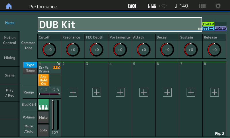
First you’ll select the Performance to create the drum loops. I have selected the Performance “DUB Kit” Press [CATEGORY SEARCH], selecting the “Drum/Perc” Category then selecting the “DUB Kit”(Fig.1 & 2):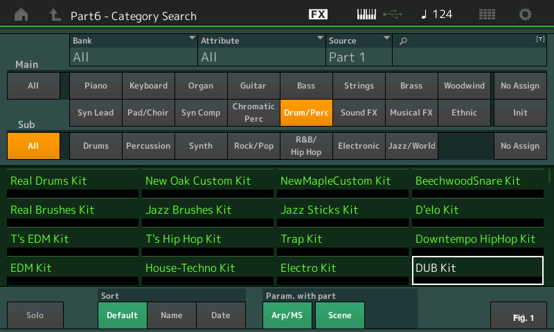
Now I want to create some 8 measure MIDI drum loops using the Song Performance recorder. Pressing the [RECORD] button on the transport opens the “Play/Rec” screen on MONTAGE. I made a change within the “Rec Quantize” setting, which will take everything I play into the Song Performance Recorder and quantize it to the nearest 16th note (Fig. 3).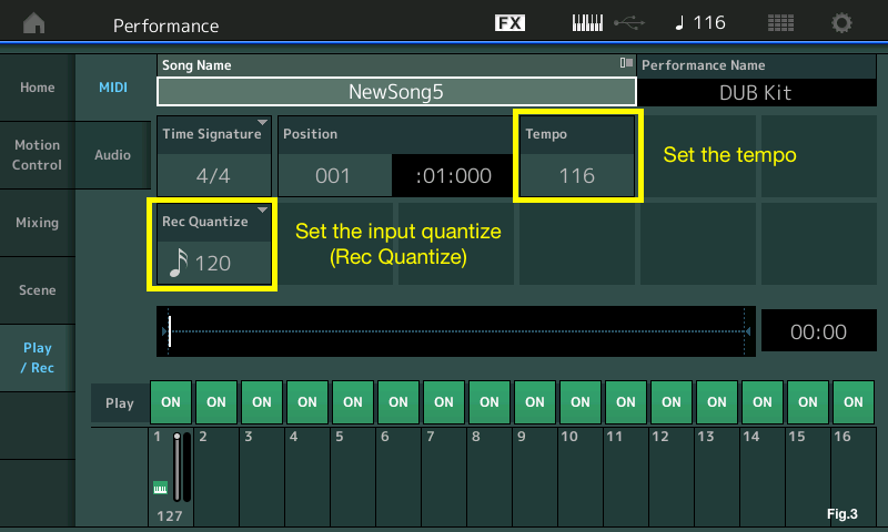
Since I am creating a Trance-type EDM groove, using the Rec Quantize setting will work great. Note: Every time the [RECORD] button is pressed from the main Performance screen, a new song is automatically created with the name “NewSongX” where “X” is the next number available. Once I am done with this recording I’ll name it “Blakeloop1”.
I first recorded the kick drum pattern for 8 measures. After making that first pass, you will notice the appearance of the Loop settings in the center display of the screen. New in firmware 1.20 is the ability to turn the Loop function on and set Loop Start and Loop End points. Since this is an 8-measure drum loop I set my loop points this way (Fig. 4):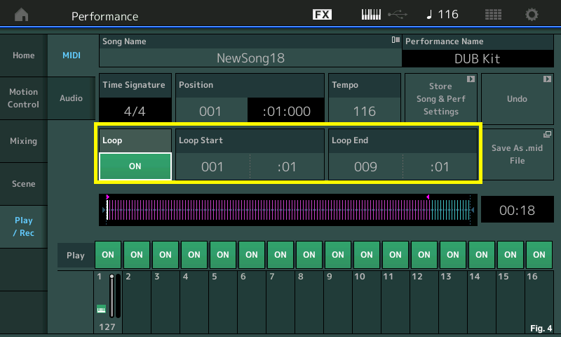
Although Loop recording is not implemented in MONTAGE, the Loop playback feature is a nice addition that allows you to listen to how the Loop will play once it is converted into a User Arp. Now I am ready to make a few more additional record passes to create my drum loop. Since there is already music data on the track, pressing [RECORD] now allows you to select from three different recording modes: Replace, Overdub and Punch-in. For the next few passes I select “Overdub” (Fig. 5):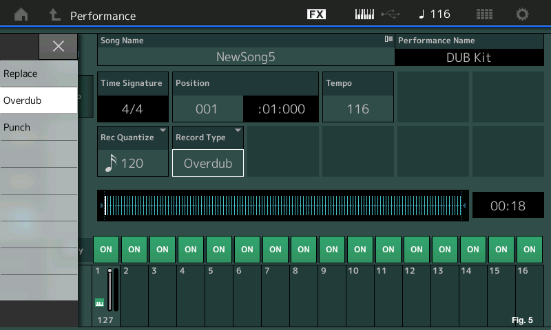
Step 2: Rename the song and store Song and Performance Settings
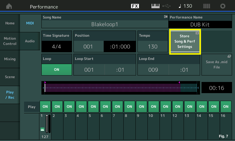
Now that I have my drum loop ready to go, I will first rename that file as “Blakeloop1” by touching in the “Song Name” box and renaming. Notice that this process is also how you go about creating a User Arp, which is coming in the next step. After renaming, press “Store Song & Perf Settings” to register the Performance “DUB Kit” to the song “Blakeloop1” (Fig. 6 & 7):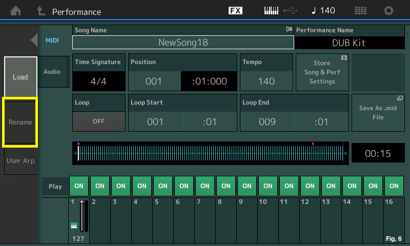
After I save “Blakeloop1”, I press the [PERFORMANCE (HOME)] button to return to the main “DUB Kit” Performance screen. To begin the process of creating the next drum loop, just press the [RECORD] button on the transport. This will automatically create “NewSongX” where “X” is the next number available. To create the next 7 loops, I repeat the process outlined in the first step, subsequently naming each loop “Blakeloop2”, “Blakeloop3”, etc. Each loop is saved as a song and viewable by pressing [UTILITY], selecting “Contents/Load” and selecting “Song&Perf” in the “Content Type” pull-down (Fig. 8):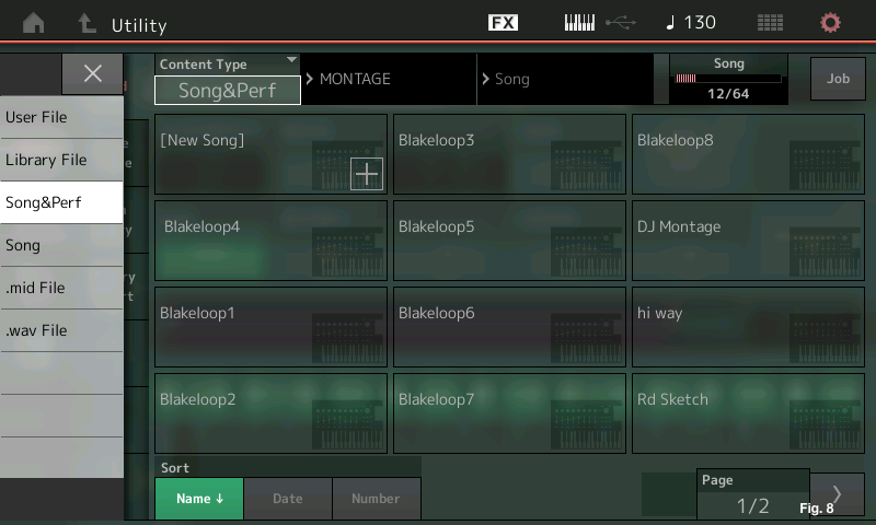
Step 3: Create the User Arps
To create the User Arps, I will start by loading “Blakeloop1” (the same screen as in Fig. 8) by selecting it in the Touchscreen. Once loaded, touch the Song Name on the screen and select “User Arp” from the choices that appear on the left side of the Touchscreen. When this is selected the following will appear (Fig. 9):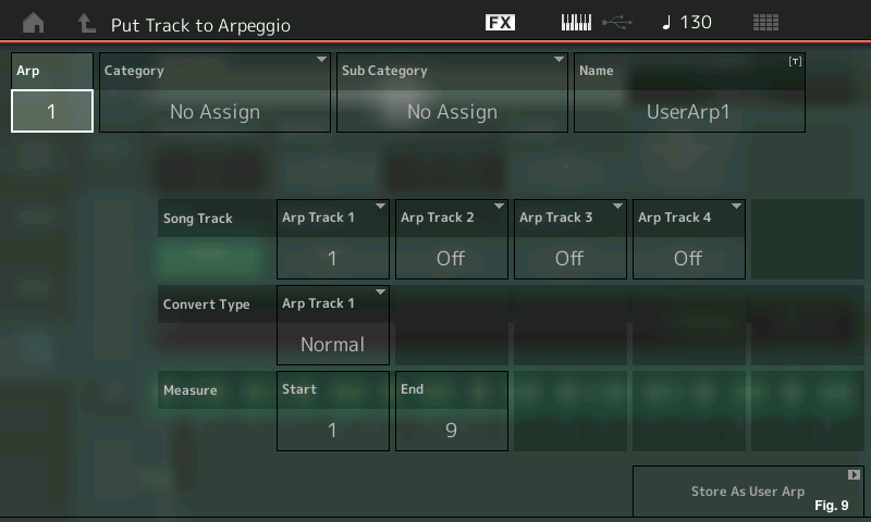
Here you can assign a Category (Drums/Perc is what I selected), a Sub Category (Techno/Trance is what I selected) and a Name (I named this “BlakeArp1”). This is just a drum loop on a single track so I will leave the “Song Track” area as is. Below the “Convert Type” is the “Measure” where I can set the Start and End points of my User Arp. This will automatically correlate to the ranges set in the Song, but I can also change these to any number from 1 to 999. That’s right: If I needed to I could create a 999 measure-long Arp! If I were creating an ambient sonic landscape, this could come in handy. Once these are set, the next thing I need to do is to change the “Convert Type” by touching the box and selecting “Fixed” (Fig. 10):
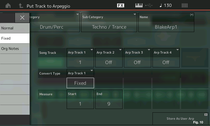
The choices are as follows:
Normal: The Arpeggio is played back using only the played (fingered) notes and its octave notes.
Fixed: Playing any note(s) will trigger the same MIDI sequence data.
Org. Notes (original notes): Basically same as “Fixed” with the exception that the Arpeggio playback notes differ according to the played chord or key.
For a drum loop, it is important to choose “Fixed” if the intention is to playback the drum loop exactly as it was recorded! Any of the other choices will produce different results depending on what note is played. In the first article of the “Arpeggio Making 101 for MONTAGE” there is a much deeper explanation of these types with a great educational tutorial that shows the differences. Once I have created each of my User Arps, it’s time to place them into the Performance “Moving Floor”.
Step 4: Place the User Arps into the Performance “Moving Floor”
The first thing I will do is call up the Performance “Moving Floor”. What I want to do is replace the existing drum Part with the “DUB Kit” and replace each of the 8 Preset Arps with my User Arps. To do this, simply touch the existing Part at the very top of the Part channel and the selections to the left appear. Select “Delete” and remove the existing Part (Fig. 11):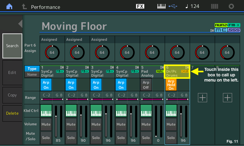
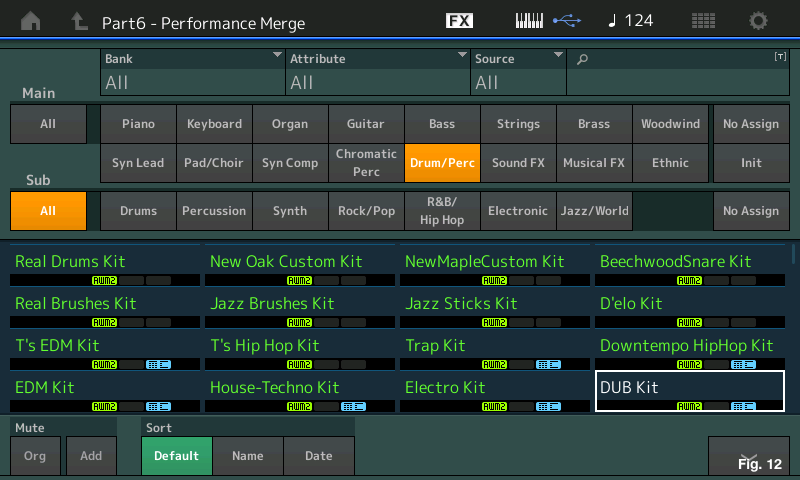
Now that I have deleted Part 6, I will replace it with “DUB Kit”. Touch the box with the “+” in the middle to call up the Performance Merge screen and replace Part 6 with “DUB Kit” (Fig. 12):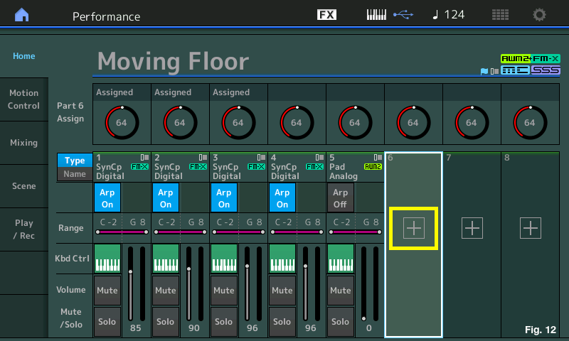
This Part has Preset Arps that are active when it is merged with this Performance. I need to replace those with the new User Arps. To do this, touch the Part in the same manner as in Fig. 11 but touch “Edit” instead of “Delete” to drop into Performance Part Edit. From here, I’ll touch “Arpeggio” on the far left in the Touchscreen, then I’ll touch “Individual” to see a listing of each of the 8 Preset Arps assigned to the Part (Fig. 13):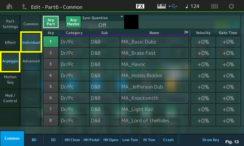
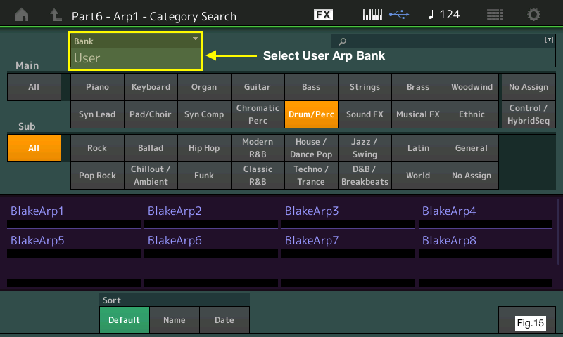
To replace the Preset with the User Arpeggios, touch the first slot in the “Category/Sub/Name” area of the Touchscreen. A dialog will appear on the left. Touch “Search” to drop into the Arpeggio Library. Finding the User Arpeggios is easy. Touch the “Bank” pull-down in the upper left of the Touch screen and select User, then touch the “X” to close that window. The process is outlined below (Fig. 14 & 15):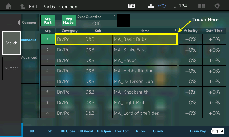
I did this 8 times in total, dropping into Arp Category Search, selecting each of my User Arpeggios and replacing each one. You can also simply touch in the “Category/Sub/Name” area and spin the Data Dial (directly to the right of the Touchscreen) to the very end of the Arpeggio list. The User Arpeggios will appear at the end of the list after you move through the Preset Arpeggios. With the Preset Arpeggios replaced with my User created ones, my screen now looks like this (Fig.16):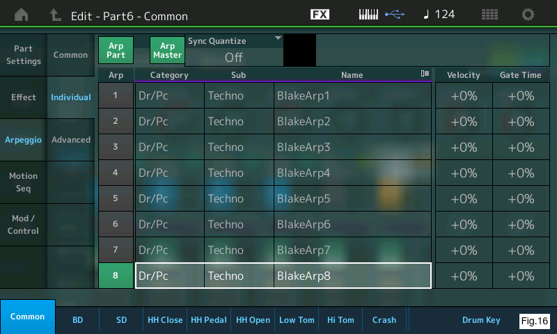
Step 5: Make a few edits to the effects and the routing of some of the drums in the DUB Kit
A quick word about effects and routing: Just like all the Parts of a Performance, this Part has two Insertion effects available in addition to the System effects that are available to ALL the Parts. All Parts have access to the Variation, Reverb, Master FX and Master EQ. With regard to the Variation and Reverb effects, each Part has individual send levels to increase or decrease the amount of that effect to the individual Parts (The Master FX and EQ are applied to the entire Performance and do not have sends). Drum Parts allow some cool routing and individual drum edit options within MONTAGE.
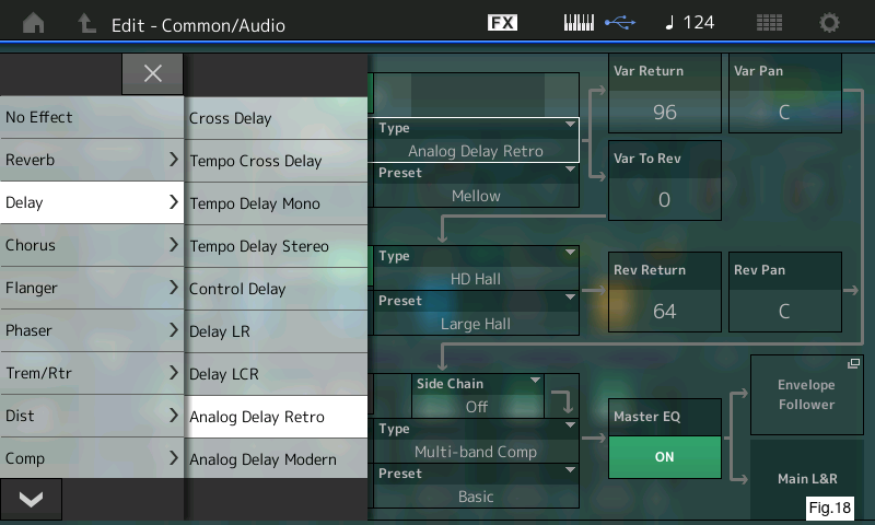
I made a few changes to the Performance effects and the routing of individual drums within the DUB Kit in Part 6 as well. The first thing I wanted to do was change the overall Variation Effect from the “Tempo Cross Delay” to the “Analog Delay Retro”, which simulates a vintage tape echo and has a great sound. This is accomplished by pressing [EDIT], pressing the [COMMON] button located underneath the [LIVE SET] button (to ensure that I am at the top “Common/Audio” level of the Performance) and touching “Effect” then “Routing”. Touching in the “Type” area of the Variation Effect area of the routing page calls up a pull-down menu listing all of the available effects. Fig.17 and 18 below show the original Variation effect compared with the changed one: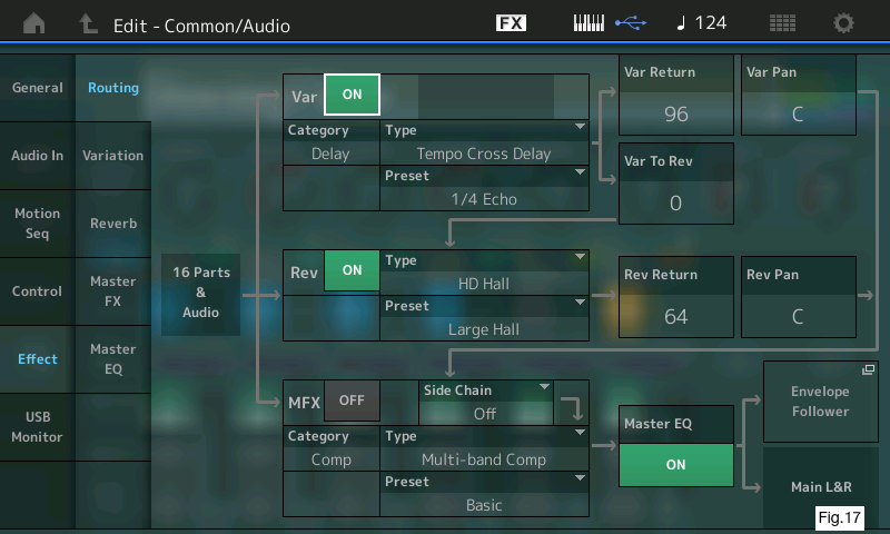
What I want to do is route a few of the individual drum sounds in the DUB kit through the Analog Delay Retro Variation effect. The first thing I will do is turn off the Arpeggio playback by pressing the [ARP ON/OFF] button all the way to the left next to the master volume slider (it is off when the lighted button is off), then select Part 6 to make this specific Part edit. Additionally, I will want to solo this part, so I press the part [SOLO] button on the far right. At this level I can make edits to the entire drum part (Part Common) or to individual drum sounds (Part Element). Note the difference in Fig.19 and 20 below: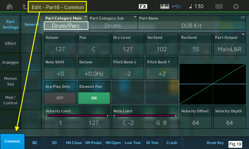
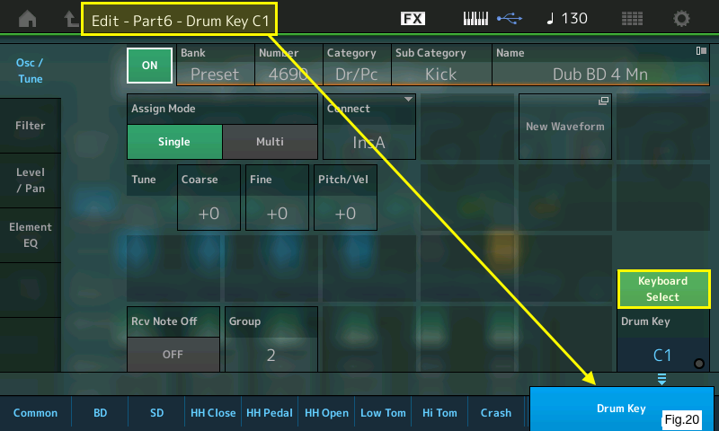
A great user interface feature is the “Keyboard Select” option that appears when you are at this level (highlighted in Fig.20 in the lower righ). When you touch this option in the screen, pressing the key associated with an individual drum sound shows the settings for that sound. You have three options:
- “Thru” which bypasses the Insertion Effects entirely and allows sends to the Reverb and Variation effects per individual Drum Key.
- “InsA” which routes individual Drum Keys through Insertion Effect A.
- “InsB” which routes individual Drum Keys thought Insertion Effect B.
Before moving on, I’ll take a moment to look a little more closely at the Common Effect routing page for Part 6. Fig.21 shows this below and I’ve highlighted some of the important routing options: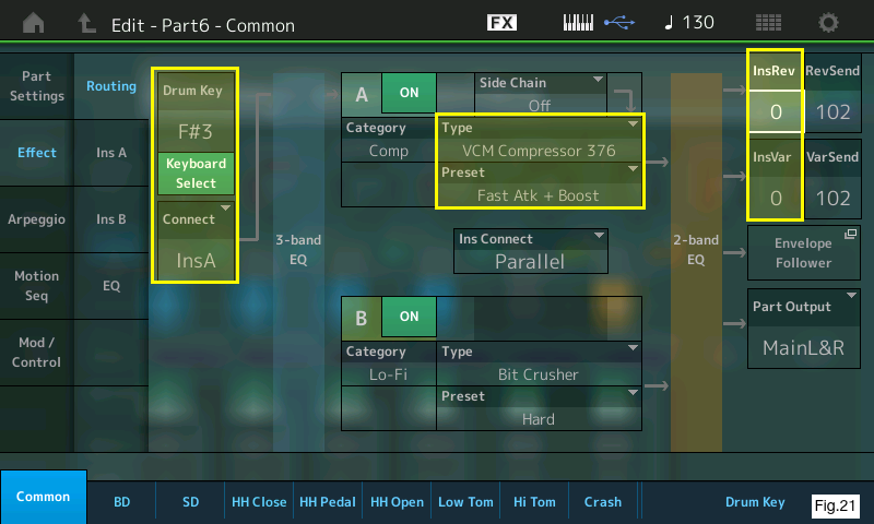
Note that you can use the keyboard to select individual notes and routing here as well (highlighted on the left). In Fig.21 I have F#3 selected (“Dub BD 6 St”, the primary bass drum sound I am using). I want this drum to have no Reverb or Variation effect, but I do want to route this through the VCM Compressor (set to a fast attack and boost preset as highlighted in the middle) so I have set the Reverb and Variation send level from the Insertion effect to “0” (highlighted on the right). This gives me the powerful kick drum sound with no Reverb or Delay applied.
Now I’m going to look at individual Drum Keys more closely by touching the “Drum Key” tab in the lower left part of the screen. I want to route two of the drum sounds—one on G1 (“Flam Mn”) and another on F2 (“Dub Fx2”)—and route them to the Variation effect only. First I’ll select the sound on G1 from the keyboard and touch the “Connect” pull-down located in the middle of the screen (Fig.22):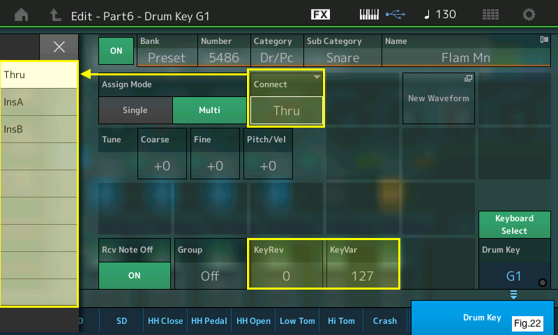
You can see your Connect options in the pull-down on the left. For the “Flam Mn” sound on G1 I have selected “Thru” (no Insertion effect) and I have the Variation send (KeyVar) set to 127 for the “Flam Mn” sound on key G1. This gives me the “Analog Delay Retro” effect applied to that single key. Cool! I’ll do the same to the “Dub FX2” sound on F2.
There are other edits that are available on a key-by-key basis for the drum kits in MONTAGE. In addition to effect routing, each drum key can have its own individual tuning, velocity controlled pitch changes, resonant filter, pan positioning, amplitude envelope, and EQ. (Fig.23):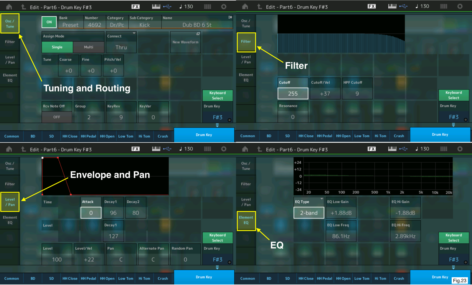
I created three audio recordings for this tutorial. I first recorded everything into the MONTAGE Song Performance Recorder then recorded just the audio into Cubase.
UserArpSolo: In this first one I played each of the individual User Arps soloing Part 6 and moving through each of them every 8 measures at 130 bpm (the tempo I chose for my version of the “Moving Floor” Performance). Note the two drum keys that have the vintage delay effects applied.
MovingFloor: This is the original “Moving Floor” Performance (124 bpm) with the Preset Arps.
MovingFloorUserArp: This is my version of the “Moving Floor” Performance using my User Arps (130 bpm) and mixing changes.
The dramatic changes in the synth parts on both the full mix Performances occur when I move the Super Knob. Note the difference in the kits and the delay effect. Even though Parts 1-5 were not changed between the two Performances, the differences in tempo, User Arps, mixing, routing and the change in Variation effect from “Tempo Cross Delay” to “Analog Delay Retro” really impart a striking sonic change between the two similar examples.
Everything has been done within MONTAGE at this point in the article. Now it’s time to move my User Arp Performance from the MONTAGE Song Performance Recorder into Cubase using the MONTAGE Connect VST3 plug-in for further work in the DAW.
Step 6: Moving the User Arp Performance and Song into Cubase with MONTAGE Connect
(Please check out the first article in this series, “What is MONTAGE Connect?” for more detailed setup information on the MONTAGE Connect VST3 plug-in).
With MONTAGE Connected to the computer via USB, it is now time to capture the Performance “Moving Floor UserArp” and then move the song I created with from MONTAGE into Cubase.
After launching Cubase, I’ll first create a blank Project and create an Instrument Track in Cubase, add the MONTAGE Connect VST3 plug-in, and then capture the Performance (Fig.24):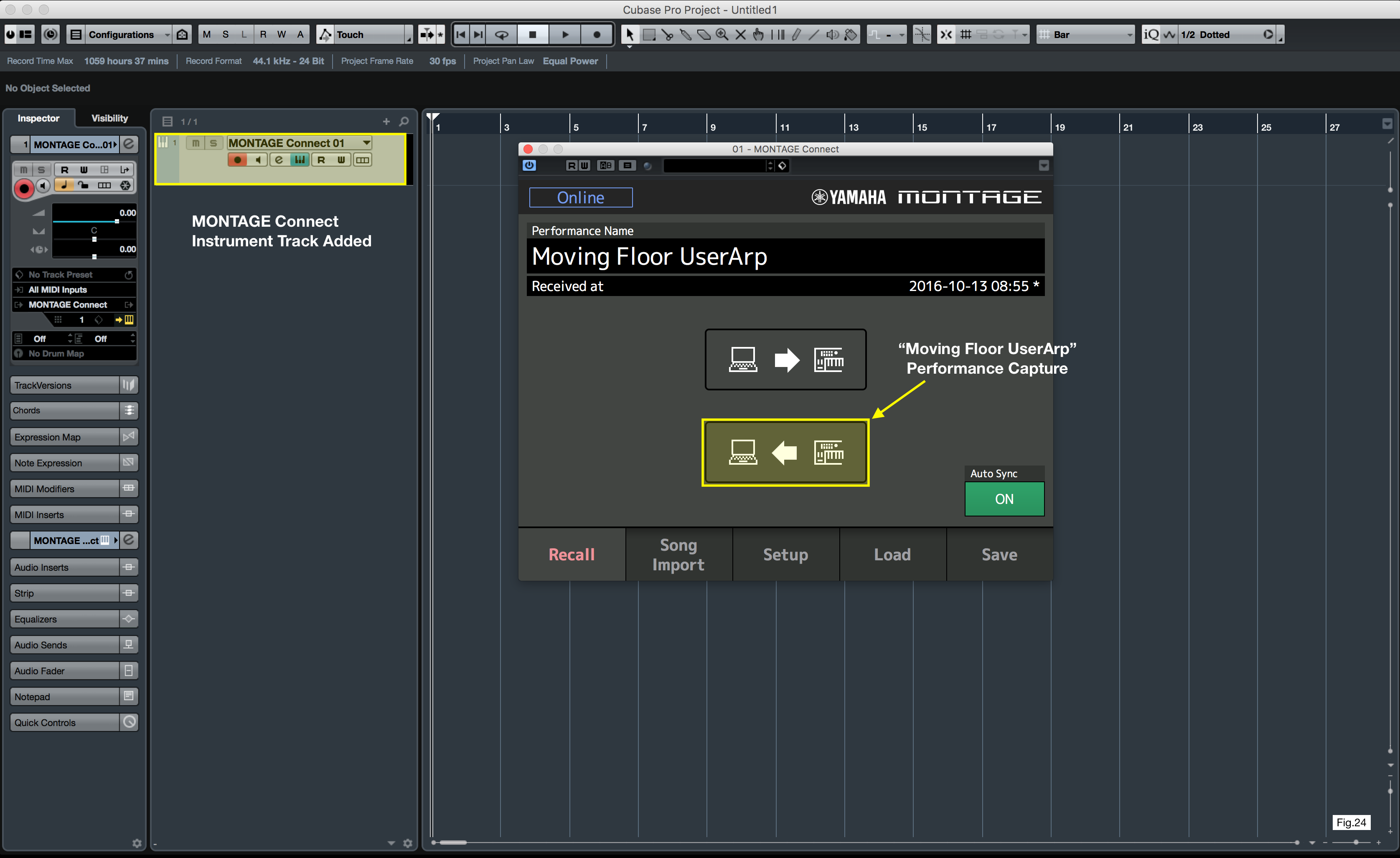
With the Performance captured it is time to move the Song into Cubase. I’ll first choose the “Song Import” tab and locate the song “MovingFloorUserArp”, then I drag-and-drop the song into Cubase’s Project timeline (Fig.25):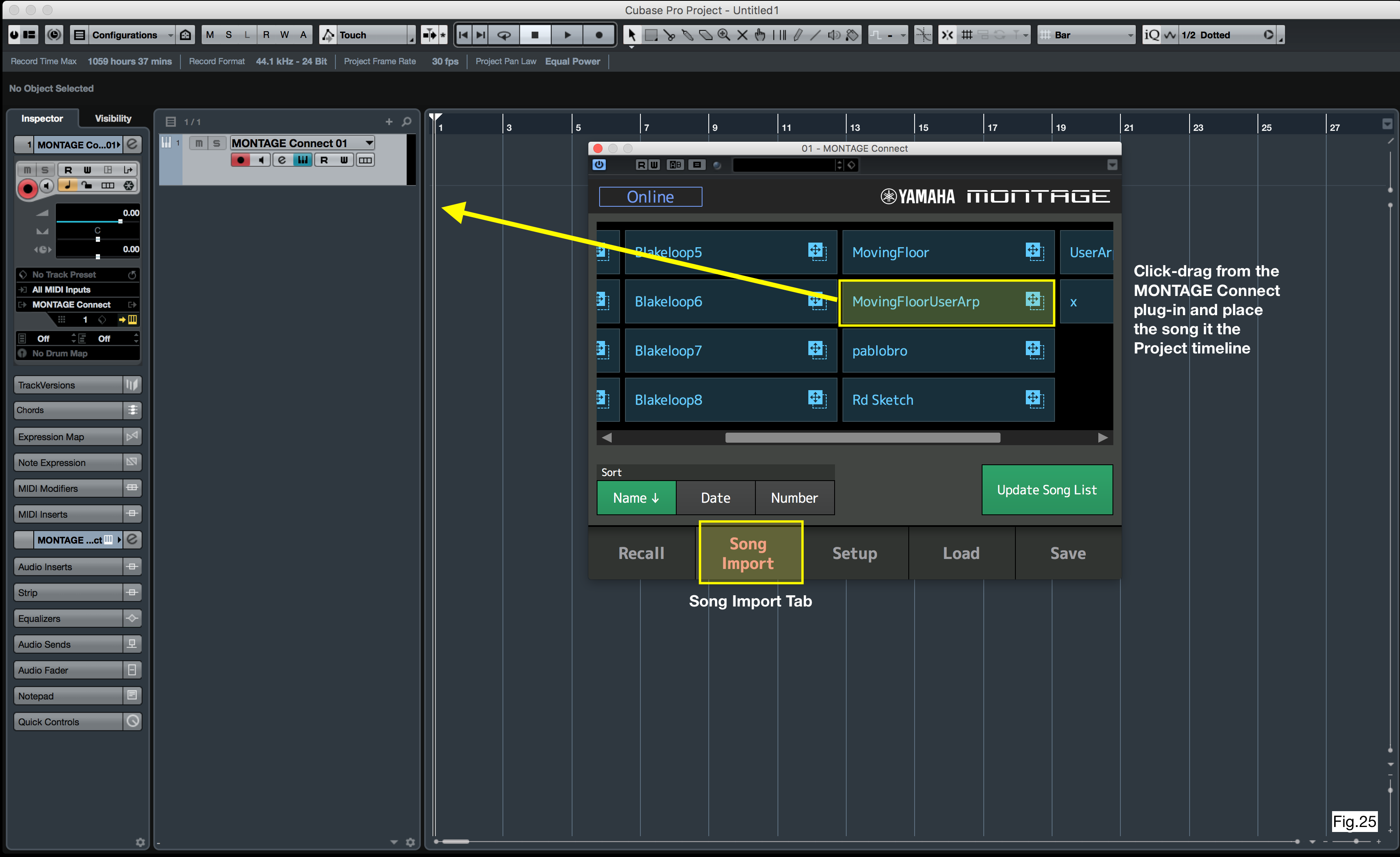
I stated this in the first article, but as a reminder I have set in Cubase’s preferences to automatically create external MIDI tracks and not create individual virtual instrument tracks. This setting is found in Cubase Preferences/MIDI/MIDI File and the “Destination” setting is set to “MIDI Tracks”. When I drag the song file into the Project the tracks are automatically created. Fig. 26 shows my tracks now existing within Cubase. I colored and named them for better visibility (Fig.26):
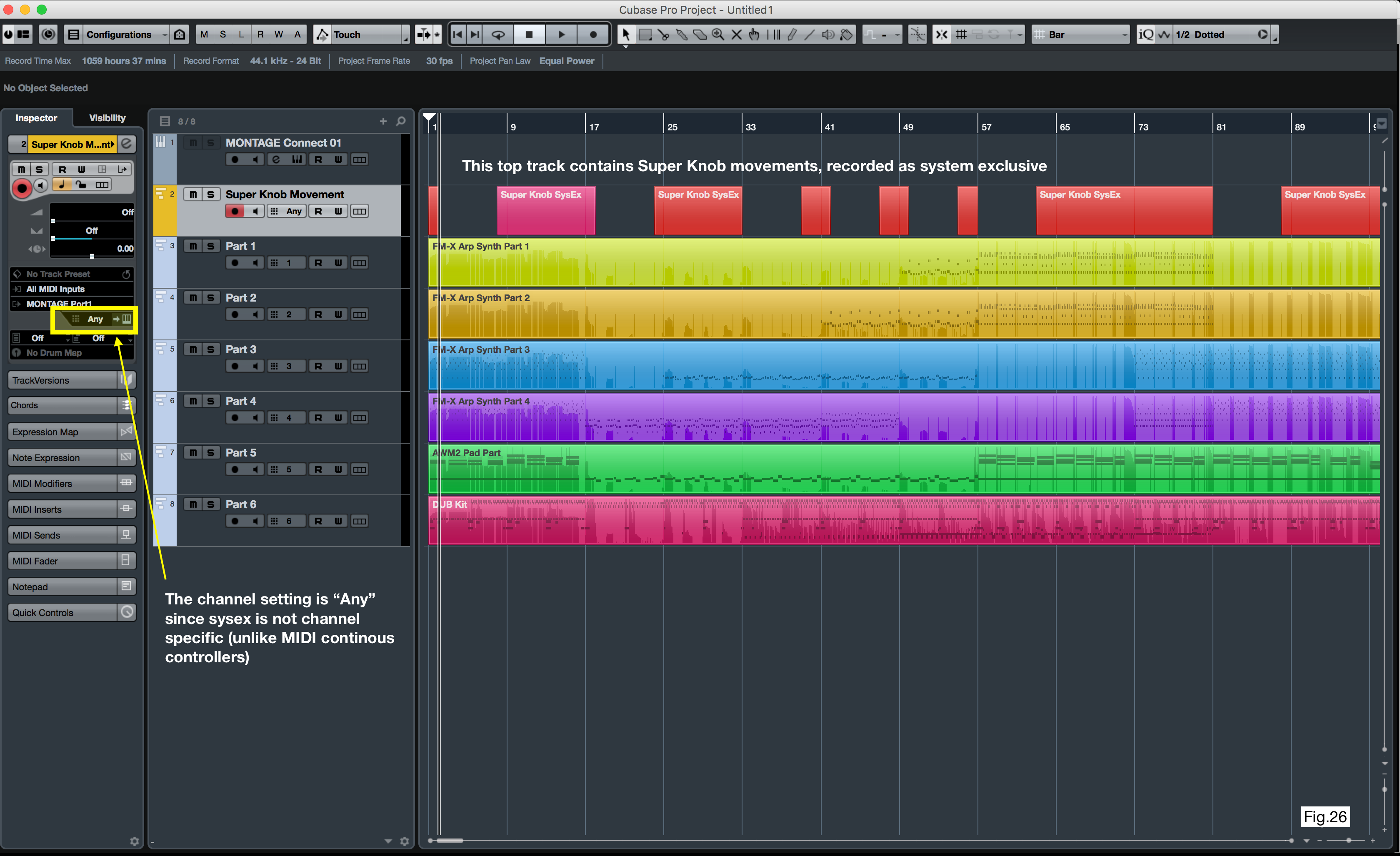
A note about Super Knob movements: With Version 1.20 of MONTAGE the ability to set a MIDI CC (Continuous Controller) was added. In this case, I left that setting to “Off” so the Super Knob movements are recorded as MIDI sysex (System Exclusive). Sysex data is not channel specific. Had I set a MIDI CC number (95 is a good one to choose) each individual track would have controller 95 data in the same track location as the top sysex track, because MIDI CC messages are channel specific. There are pros and cons found in each method. The benefit of recording as sysex data is it is not channel specific and the movements control all tracks simultaneously. The drawback is you cannot easily drop into a visual editor and simply “draw” in Super Knob movements as you can with MIDI CC data. However, if I recorded the Super Knob movement as MIDI CC all the tracks would have the same controller data appearing on controller 95. If I wanted to edit those Super Knob Movements I would have to edit each track individually which presents its own issues. For the purposes of this article, I left the Super Knob movements set as sysex and if I wanted to re-record those movements I would delete that data in the top sysex track and record again (old school…If I make a mistake, I will rerecord).
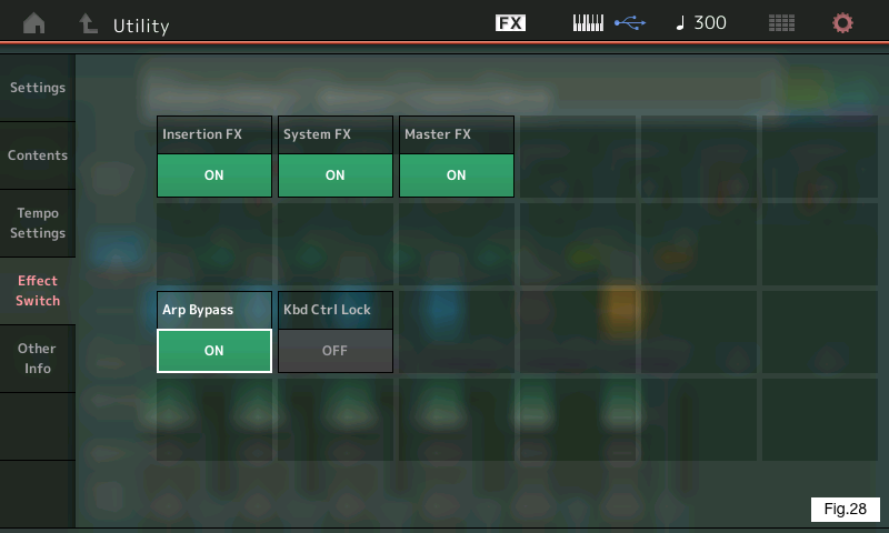
There is one final and very important step when playing the recorded Arp data back from the Cubase. If you do not turn off the Arpeggiator and try to play back the imported song from Cubase the MIDI data coming in from Cubase will retrigger the Arps and the result may be unexpected (to put it mildly). Fortunatel, this was thought through with Version 1.20 with global Arpeggio bypass. Pressing and holding the [SHIFT] button while touching the [ARP ON/OFF] button enables global Arpeggio bypass. This is a must if you want your song to playback exactly as it was originally recorded! The Arpeggio bypass shortcut is engaged by pressing [UTILITY] and touching the “Effect Switch” Tab on the left (Fig. 27). In Fig.28 you can see where the Arpeggio Bypass function is located under [UTILITY]/Effect Switch: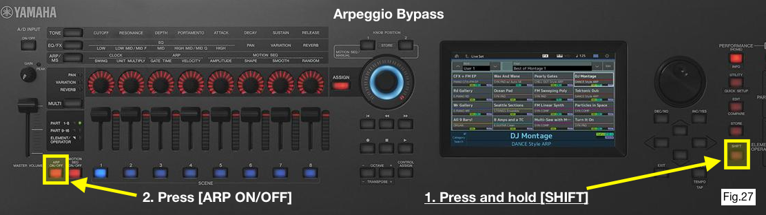
I hope this article helps with your own production with MONTAGE. Stay tuned for more workflow articles coming soon!
In the meantime, want to discuss or ask questions about this article? Join the conversation on the Forum here.