Mastering MONTAGE 9: Controller Box Switches

The video below is a great accompaniment to this article. Check it out:

PERFORMANCE 10: ControllerBoxSwitchA

Sometimes it is needed to make control assignments only to specific Elements within the AWM2 PART (or to specific Operators within the FM-X PART). In the default setting the control assignments are valid for all Elements of a Performance. The individual assignments for Elements can be done on the Controller Set screen – you can select the Element for Destinations that allow individual selection. (Please note: The Live Set that is used in the Mastering MONTAGE series is located here.)

This means that all used control settings made in the Part Controller Set are initially enabled. If you select a parameter that allows for individual Element assignment, you must OPT OUT for the individual Element. The default is that an ELEMENT is set to OPT IN. In other words, if you select a parameter Destination that does offer individual ELEMENT assignment, the Elements are initially set to active (ON) by default. If you don’t want to control an Element turn its individual Switch OFF. Of course, if you do not select the parameter Destination, its being ON or OFF is of no consequence, because you will not be changing anything.

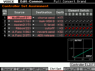
For better understanding it may help to compare this function with the corresponding function of MOTIF XF, which is the “Element Switch” in the Controller Set Assignment.
XFCtrlSet
As you can see in the displayed screenshot the Effect parameters are unchecked or greyed out, because they cannot be used individually for Elements. This is because of the selected Destination. The entire sound (all Elements together) are routed through the selected destination (Effect). “InsA-HSH G” (Insert A – High frequency Shelving Gain) which is an EQ and “Reverb send” are situations where the entire program is processed, it is not a possibility to select just a single Element.

In CONTROLLER SET 4 and 6 (Destinations “cutoff” and “AEG release”, respectively) are checked for all Elements. Here you have a choice, and all Elements are opting in.

In CONTROLLER SET 3 (Destination “Element Level”) is checked only for Element 8. The programmer would have had to uncheck Elements 1-7 in order to OPT OUT.

A CONTROL SET on the Motif XF consists of a SOURCE (physical control) and a DESTINATION (target parameter). The DEPTH dealt with the application of the controller both range and direction, and for those Destinations appropriate you were provided the option to select specific Elements individually. The MOTIF XF had only 6 Control Sets; MONTAGE provides 16 Control Sets per PART and an additional 16 for the COMMON/Audio level of editing; plus new parameters like Curve Type and Polarity and advanced shaping tools designed so you can customize the application of controllers.

These new shaping tools exponentially increase the DEPTH function as was available in the Motif and MOXF series. DEPTH does not have to be linearly applied. In fact, you can completely customize the shape of how the application of a controller is applied. You can manually apply it or automate its application. This is at the core of the Motion Control Synthesis Engine.

The layout is a bit different. But the operation is fundamentally the same.

_ If a Performance Part doesn’t require individual Element assignments you can keep the Controller Box Switch as it is. All Element Switches default to ON
_ If you want to make individual Element assignments you have to edit the Controller Box Switch matrix.

Translation: CONTROL ASSIGNMENTS are easy to deal with because they are seen within the PART’s Element/Operator view and are made as you think about them – which is intuitive. It is very much like patching a modular synth, in that as you build your sound, you make the necessary connections/assignments. The key thing here is the Destination (parameter) determines whether or not the Element/Operator Switches appear or not. Obviously, some Destination parameters are PART destinations (affect all Elements or Operators together like common Volume, Send to Reverb and Variation, etc) and others are individually switched per Element or Operator (like Element Level, Element Pan, AEG, FEG and PEG parameters, Cutoff, Resonance, LFO etc.). This can be seen as equivalent to the kind of ‘patching’ you would do in voltage controlled analog synthesizers, if you had a wall unit full of modules. Think about all the individual envelopes you can control within the 8 PARTS, each with as many as 8 Elements (if AWM2) or each with 8 Operators (if FM-X)

PERFORMANCE 10: ControllerBoxSwitchA
This example includes a simple Super Knob morphing between two different organ Waveforms within a single Part:
Element 1 = Gospel
Element 2 = 1st Four Draw

Instead of the organ sound occupying a Part, here each B3 sound is a single Element within the same Part.

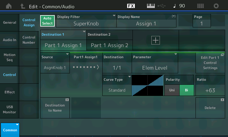
Element 1Gospel is assigned to the right (fully clockwise) position, Element 2 1st Four Draw is set to the left position of the Super Knob. In the center position you will hear a mix of both. First step, for the Super Knob assign is the assignments in the “Common/Audio” Controller Box: The first two Knobs (Assign1 and Assign2) are set to link with PART 1 on this upper Common/Audio level (the Super Knob level). Instead of morphing between PARTS, we are now working within a single PART by manipulating individual Elements (since this is an AWM2 sample based progrm). Each Element references a Waveform. A Waveform organizes a set of samples mapped to respond across the keyboard at specific pitches and velocities. 

From the HOME screen:
Press [EDIT].
Press the upper [COMMON] button; Select “Control” > ” Control Assign.
With the AUTO SELECT (green) active you can view the assignments either by moving the Knob itself or setting the DISPLAY FILTER = SuperKnob:
SK ContSw

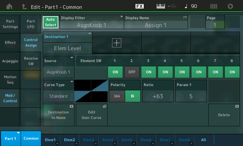
Next follow the assignments in the Part Controller Box, which is basically the same as morphing between Parts, but this time using the Element Level as destination. Below, we can take a look at the two PART 1 destinations.

Press the [PART SELECT 1/1] to view “Edit – Part1 – Common”:
Select “MOD/CONTROL” > “CONTROL ASSIGN”.
Ensure that “Auto Select” is active (green).
Move ASSIGN KNOB 1:
DSNAP 45

Move ASSIGN KNOB 2:

DSNAP 46

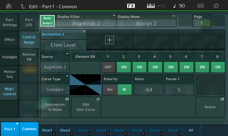
(Top screenshot) Assignable Knob 1 (Ratio +63) = Element Switch 1 ON, Element Switch 2 OFF
(Bottom screenshot) Assignable Knob 2 (Ratio -64) = Element Switch 2 ON, Element Switch 1 OFF

It should be noted here that, you can STORE the position of the Super Knob with the PERFORMANCE. So if you want this Performance to come up with the 1st Four Draw Element alone, you would store the Super Knob at a value of 0. If you wanted the Gospel Element alone, you would store the Super Knob at a value of 127. And finally if you wanted to recall the sound with both set equally, you would store the Super Knob at 64, or the balance you desire.

From the PERFORMANCE (HOME) screen:
Touch “Motion Control” in the main screen’s left column.
Touch “Super Knob” in the second column.
SUPER KNOB value is in the lower right corner.

SOURCE:DESTINATION CONTROL ASSIGN Shortcut:
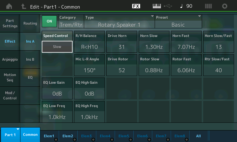
This is a good example to illustrate how easy it is with MONTAGE to assign a parameter (Destination) to a controller (Source). While up until now, we have been going through the screens where this all takes place on the “scuba diving” tour. The following is a quick and easy assignment – for the snorkelers. Say you’ve selected the Rotary Speaker TYPE as Insert Effect “A” and you want to assign Rotary Speaker: Speed Control to the MOD WHEEL. (Notice this Performance does not have it assigned).

Start from the HOME screen (touch the icon in the upper left corner):
Press [EDIT].
Press [PART SELECT 1/1] to view the PART 1 parameters.
Touch “COMMON” (blue) in the lower left corner or the screen.
Touch “EFFECT” in the left column.
Touch “INS A” to view the parameters of the Rotary Speaker.
Move the cursor to highlight Speed Control (shown):
DSNAP 47

Press the [CONTROL ASSIGN] button (located to the left of the screen below the Super Knob), which is now illuminated. The Destination Parameter will appear in the screen and it will tell you to activate (move) the controller you wish to assign:
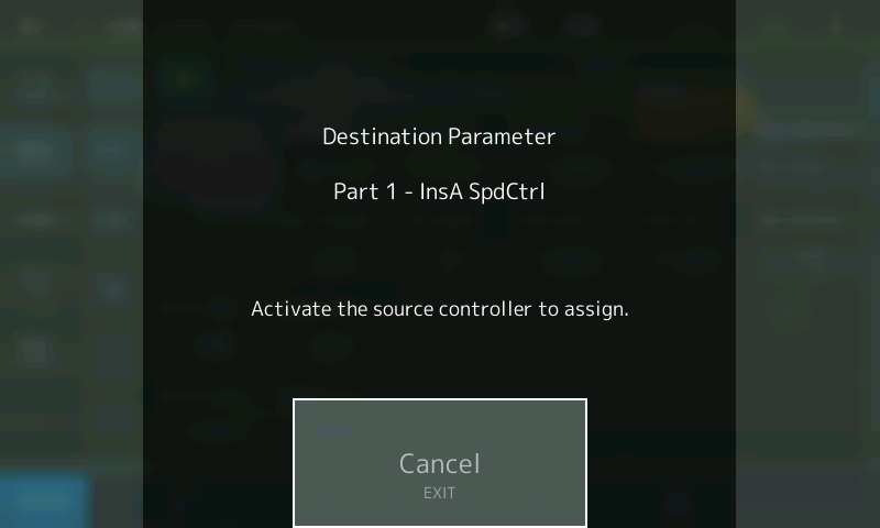
CtrlAsnInfo

Move the Mod Wheel:

DSNAP 48

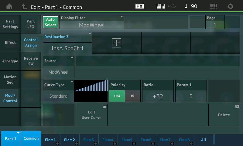
Done! It takes you immediately to the Controller Assign screen where you can tweak the Controller response (Depth) and/or Delete the assignment (Lower right corner of this Control Set screen). Notice that the Element Switches do not appear as they are unavailable – because all Elements will be affected by the application of the Rotary Speaker Speed change. 

In the OVERVIEW you can now see how the MW (Controller) is linked to PART 1 (magenta):
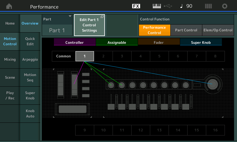
DSNAP 49

The [CONTROL ASSIGN] button, located to the lower left of the screen below the Super Knob, will glow whenever you move the cursor highlight to a potential assignable parameter. This allows you to rapidly assign, then scale and shape the application of that controller.

Extra Credit: NEW ROTARY SPEAKER TYPE
With PART 1 selected try substituting the new “Rotary Speaker 2” Type for the one above:
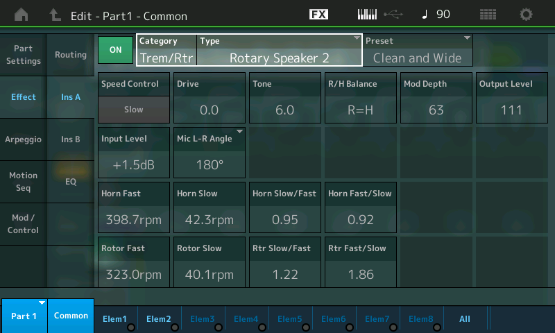
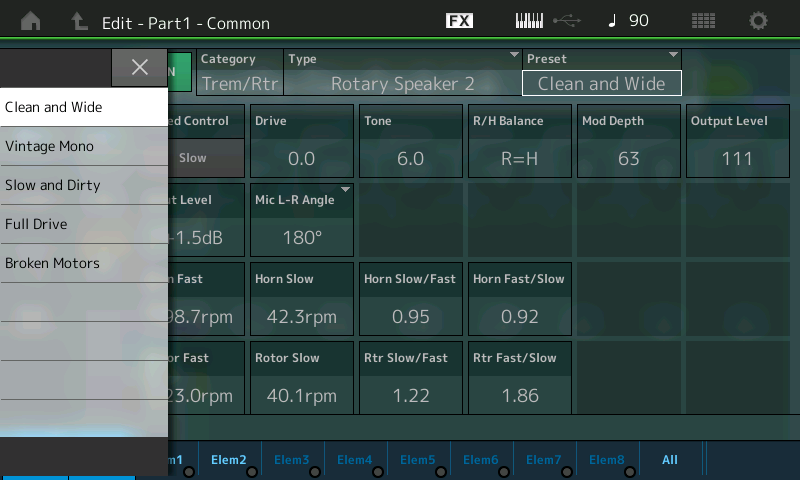
DSNAP 50

Tap the PRESET box to view the various starting points. A pop-in menu will appear; Use the DATA WHEEL or touch the Preset you would like try:

DSNAP 51

If you have any questions or comments about this article, please join us to discuss them on the Forum here.

Catch up on the previous article in the series – Mastering MONTAGE 8: Assignable Knobs.

Check out the next article in the series: Mastering MONTAGE 10: Side Chain Modulation.

Mastering MONTAGE 10: Side Chain Modulation


Side Chain Modulation
PERFORMANCE 11: Side Chain Comp
PERFORMANCE 12: Side Chain Arp
PERFORMANCE 13: Side Chain RingMod

The following Insert Effect Types have a Side Chain Input Routing option, when a source, called the ‘Side Chain Part’, is selected for the Insert Effect in the Part Effect window:

– VCM Compressor 376
– Classic Compressor
– Multiband Compressor
– Ring Modulator
– Dynamic Ring Modulator
– Dynamic Filter
– Dynamic Phaser
– Dynamic Flanger

Insert Effects are those that are unique to the instrument sound occupying the PART. Each of the MONTAGE 16 synth PARTs plus the A/D input PART has its own pair of Insert Effects – which are customizable on a per PERFORMANCE basis. These can be configured in series or in parallel and can be routed to from within the synth engine. Significantly, the Insert Effect is not shared by any other PART, and is routed “inline” with the particular instrument sound, allowing you to control this Effect on a per PART basis with assigned physical controllers.

Please note: The Side Chain Modulation is immediately active upon selecting a Side Chain Part for the respective Insert Effect, even if the Side Chain Input Level is set to zero. The zero level is an offset value, which can be increased or decreased for controlling the depth of the Side Chain Modulation.

Translation: To avoid unintended Side Chain Modulation, basically, the Side Chain Part selections for Insert Effects should be left in the default condition; that is, set to OFF. A Part selection should be made only for activating the Side Chain Modulation. To understand this, the SIDE CHAIN connection option allows audio signal from the source PART to enter and influence (modify) the output of the current PART via its assigned INSERT EFFECT. So just by making the connection audio is routed in, what we can do is increase or decrease that audio. If you do not want audio signal to route via the side chain, simply leave the parameter set to OFF.  

The PART with the INSERT EFFECT Side Chain Input will be modified by the PART you route in via this ‘side’ input. 

The source signal becomes the modulation energy. Its audio creates the nature of modulation – the energy is used to make changes in the target destination parameter. In the case of a compressor you can have the audio pulse of one Part influencing the target destination’s audio. The Ring Modulator Side Chain can be used to add radical detuning on cue from the pulse of the audio source; the Dynamic Filter, Dynamic Phaser and Dynamic Flanger each add a distinct audio result in response to the selected SOURCE. We can only give you some very basic examples, to get you started; like patching in a modular synth, the actual results will really depend on your creative imagination – what you choose as the source and what you choose as the sound being modulated. We’ll show some typical examples, but these are what’s already been done (and is now popular). Experimentation is required here for best (unique) results. The best way to understand this is to hear it, then explore the settings:

PERFORMANCE 11: Side Chain Comp
This example shows a very typical Side Chain Compression result, where a “pumping sound” is created for a synth pad caused by the input of a bass drum groove. The Pad sound is interrupted by the input of the bass drum. To be clear: Part 1 contains the PAD sound and Part 2 contains the arpeggiated Kick Drum. The Kick drum causes the Pad to “duck” in volume. So the Compressor is applied to the PAD in PART 1, and instead of using the Compressor to respond to the attack and release of the Pad itself, we are using Part 2’s audio to ‘duck’ the Pad (Side Chain). SideChainCloseUpIn Part 1’s Compressor you would set Part 2 as the input (Side Chain Input). Side Chain uses the compressor’s Gain Reduction function to create an envelope. The Kick and the Pad cannot happen at the same time when fully applied. (Please note: The Live Set that is used in the Mastering MONTAGE series is located here.)
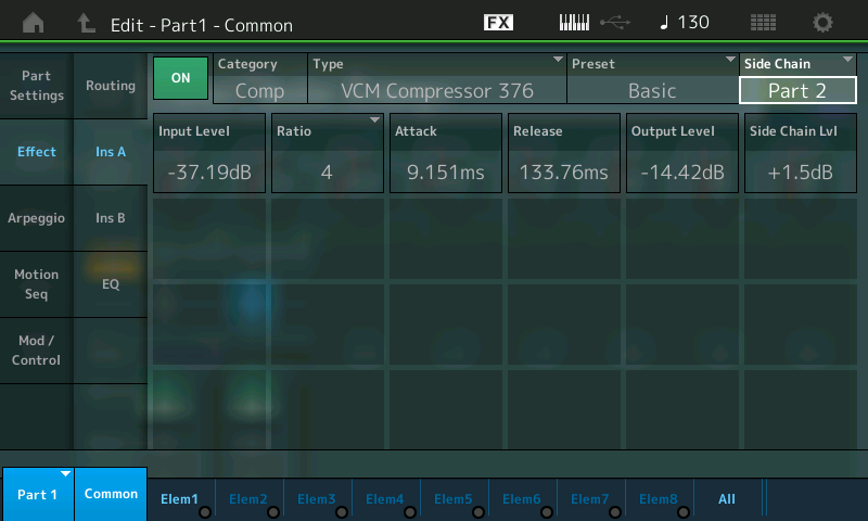
Only two settings are needed for programming the Side Chain Compression of PART 1.
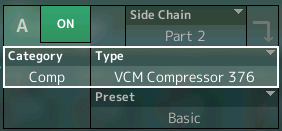
First, the Side Chain Part must be selected Insert Effect “A” in the Part Effect window. It is “Part 2”, in this example, it includes the bass drum groove.

The Side Chain Input and its Level parameter are found in the MONTAGE by navigating to the PART’s Insertion Effect.

From the main PERFORMANCE (HOME) screen:

– Press [EDIT].
– Press [PART SELECT 1/1] to select and view PART 1 (Pad).
– Touch “COMMON” in the lower left of the screen, if not already highlighted.
– Touch “EFFECT” in the left column of the screen.
– Touch “INS A” in the second column.

DSNAP 63

Side Chain Input source selection and the Side Chain Lvl are found on the right side of the screen.

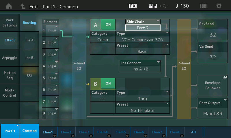
In the view of the overall Effect ROUTING, you can see where the SIDE CHAIN function is attached to the INSERTION EFFECT “A” box.

DSNAP 64

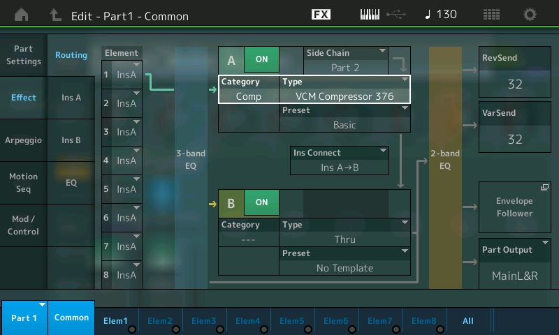
In this “Routing” screen you can see that each Element can be routed through one or the other (or neither) of the two Insert blocks (A or B). Currently, only Element 1 is active, and it is routed to the VCM COMPRESSOR 376. Notice that it passes through a 3-Band EQ pre the Insert Effects block, and there is a 2-Band EQ post the Insert Effects blocks.

You can also see the “INS CONNCT” option in the center can configure the Inserts in series (A>B, B>A) or in parallel. The “Side Chain” option appears above the Effect block where you select the Insert Effect TYPE (Insert A). You can reassign it easily here – convenient redundancy – so you can quickly and easily try out different modulation sources.

If you select one of the eight Insert Effect TYPES that support the Side Chain Modulation function, the Side Chain option box will appear. Notice the INSERT “B” (not used in this particular PART) has an empty space where the Side Chain function would apper, but nothing is there because one of the 8 TYPEs is not selected. (The option only appears when the context is proper).

Background Details: The SIDE CHAIN is a routing situation that allows audio signal from the SOURCE PART, in this case “Part 2”, (an arpeggiated Kick Drum) to create a modifying signal. In this case, the amplitude ‘shape’ of the audio of the Kick Drum, will cause the compressor to engage. Compressors are an amplifier where the more signal input in the less you get out. It, literally, compresses the dynamic range. The Compressor reduces GAIN of the signal it is applied to, however, in SIDE CHAINING, we flip the script, instead of compressing the Pad, we are going to create an envelope from that incoming signal, the Kick drum, and use it to ‘turn down’ or “duck” the Pad sound in PART 1. As the incoming signal rises in amplitude (as it attacks) it will cause the PART 1 sound to decrease (duck down) and as the Kick’s audio signal (energy) disappears, the PART 1 sound will return. For a rhythmic pulsing/pumping sound.

“Ducking” is used on the radio – where the DJ’s Voice (source) causes the music program to duck down, and it automatically returns to full volume after the DJ finishes speaking. You can control the ATTACK (how quickly it engages) and RELEASE (how quickly/slowly it lets go) of this signal creating the ducking action. The Attack Time and Release Time settings are critical to shape the results. When used for speech or singing, the Release is obviously less aburpt than it would be on a percussive signal like a Kick drum or Snare drum. Basically, set them by ear! 

And while this particular effect is extremely popular in Electronic Dance Music, exactly how you choose to use it will be a matter of experimentation and preference. Side Chain Compression is one of the most popular uses for Side Chaining. In MONTAGE, however, the options for this function are expanded – and the possibilities are many.

The Side Chain Input Level must be adjusted for Insert Effect “A”. Each SOURCE is likely to need specific adjustment, depending on exactly what you are using to create the reaction. A pre-recorded source is likely to be consistent and therefore easier to deal with, but virtually anything can be used as a source. Experiment.

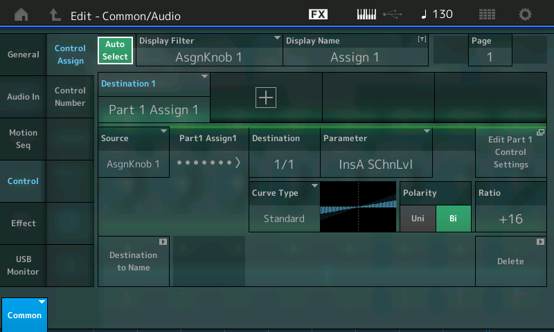
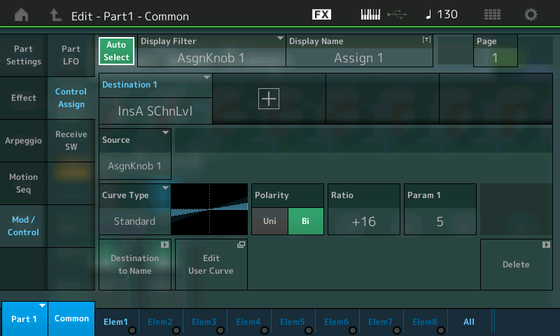
The depth (application) of the Side Chain Modulation can be controlled with the Super Knob, which is assigned to the Side Chain Input Level (InsA SChnLvl). In this manner you can use the Pad normally and then morph to a situation where the Pad and Kick are interacting at the extreme.

Here you can see the required settings in the Common and Part Controller Boxes:
Using the SHORTCUTS:
– From HOME (touch the HOME icon upper left corner).
– Press [SHIFT] + [PERFORMANCE (HOME)] to jump to the OVERVIEW screen.
– With the PART = COMMON touch “Edit COMMON Control Settings”.
Make sure AUTO SELECT is green; move Assignable Knob 1:

SK SideCh

The start position of the Super Knob is center (64). Moving to right increases the depth, moving to left reduces the side chain compression. Moving to leftmost position cancels the modulation completely.

You can return to the OVERVIEW screen by pressing [EXIT] or using the [SHIFT] + [PERFORMANCE (HOME)]
Change the PART = PART 1; touch “Edit PART 1 Control Settings”

DSNAP 66

EXTRA CREDIT: Call up factory Preset PERFORMANCE: “Mr. Side Chain”; Play and hold a nice big full chord (hold with the sustain pedal), recall SCENE #3; Slowly rotate the Super Knob from 0 towards 127. You will hear the KICK appear as you reach the 12 o’clock position, and as you increase from there, you will hear the Side Chain Compression Kick “ducks” the Pad sound. Explore further. The MW will control the volume of PAD sound in reverse. In this PERFORMANCE – the KICK drum in PART 7 is used as the Side Chain input to influence the big synth PAD in PART 1. At the same time PART 1’s Output is used as a Side Chain compressor input to influence the Arpeggiated PARTs 2 and 3. Play with this multi-dimensional interaction.  
 
PERFORMANCE 12: Side Chain Arp

This example is a variation of the previous Performance = Side Chain Comp.
But this time instead of the arpeggiated bass drum groove in Part 2, a synth arpeggio part is used for the Side Chain Compression. The audio pulses caused by the arpeggio phrase now become the modifier – you can use the ARPEGGIO Play FX to create Swing, change the Gate (duration), or offset the Velocity, even change how the phrase references the clock (tempo). 

Part 1 uses a soft string pad Waveform, which works complementary in combination with the synth arp of Part 2. In this Performance example, the synth arpeggio plays a dual role, musically complementary to the chords played and rhythmically interacting with the Pad sound underneath. 

Below we see PART 1 – Common > “Effect” > “Routing” where the Side Chain input arrives from PART 2. Notice in the lower left corner you can see the PART OUTPUT, which is sent to the MAIN L&R outputs:

DSNAP 67

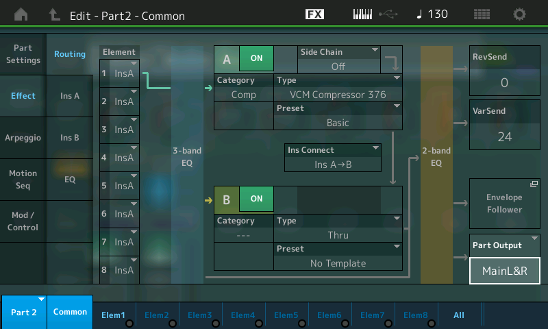
In the screenshot below, we see PART 2 – Common > “Effect” > “Routing” but the cursor is showing the PART OUTPUT… experiment by turning the PART OUTPUTfrom “MAIN L&R” to “OFF”. You will still now hear the influence of the Arpeggiated PART 2, but you will not hear the sound of the PART directly. We point this out because, it can be a very useful tool, and greatly expands how you “look” at arpeggios. You can use the rhythmic shape they create without using the musical note pattern that we typically always hear/expect from arpeggios. Remember, most anything can be a modifier in the Motion Control Synthesis Engine.

DSNAP 68

PERFORMANCE 13: Side Chain Ring Mod
This example is another variation, using the same modulation source (part 2 with synth arp), but a different Insert Effect in Part 1. Different from the complementary functionality of the previous example this time Part 1 supports the arpeggio groove, which is used as modulation source.

Extra Credit:
We will mention the VOCODER here simply because it is another INSERT EFFECT that allows for Modulation. While technically speaking, not a SIDE CHAIN in the same manner as the ones described above, one Part’s signal is fed into another via the target’s INSERTION EFFECT. 
Try the PERFORMANCE: “Chilled Vocoder” found in the PAD/CHOIR Category.
Here a Drum groove (Arp) in PART 2 is used to modify the synth Vocoder Pad sound in PART 1. The Drum groove “speaks” through the Vocoder. And a slowly evolving Sound Effect (Rainmaker) in PART 6 is modifying a string sound (PWM Strings) in PART 5 via a second Vocoder assigned to Part 5:
– Turn the Super Knob to the right from center to add more “vocoded” effect.
– Press [EDIT].
– Use the PART MUTE buttons (right front panel) to isolate just PARTS 1 and 2.- 
The direct out of the Drum Groove is assigned to OFF, so that you only hear the drums encoded onto Pad sound in PART 1.

– Use the PART MUTE buttons to isolate just PARTS 5 and 6.
– The direct out of the Rainmaker sound effect is assigned to OFF, so you only hear its output encoded onto the string (PWM Strings) in PART 5.

(Again) The “source” could be a “live” drummer, a “live” guitar player, a vocalist, a mix tape, your favorite playback device – another synthesizer – sky’s the limit.

If you have any questions or comments about this article, please join us to discuss them on the Forum here.

Catch up on the previous article in the series – Mastering MONTAGE 9: Controller Box Switches

Next article now available: Mastering MONTAGE 11: Envelope Follower

© 2024 Yamaha Corporation of America and Yamaha Corporation. All rights reserved.    Terms of Use | Privacy Policy | Contact Us