The video below is a great accompaniment for this article. Check it out: PERFORMANCE 14: Envelope Follower Using the Envelope Follower you can use the output of a Part for modulating selectable parameters of any other part. This way you can transfer the movement or rhythm of a Part to other Parts. This way of shaping the sound works especially well using percussive arpeggios or drum grooves.
In the Controller Assign box you will find the sources named “Envelope Follower 1 – 18”. The numbers 1 – 16 are assigned to the Parts 1 – 16, the numbers 17 + 18 to the A/D parts (L+R).
Translation: An Envelope is used to describe a shape. In synthesizers we talk about three main components: Pitch, Timbre (filter), and Loudness (amplitude). There are Pitch Envelopes, Filter Envelopes and Amplitude Envelopes. And what we mean by “shape” is, we need a way to describe how they behave over time. How they start, what they do while they are happening and how they disapper. In the case of this Envelope Follower we are using the Loudness (Amplitude Envelope) of one PART’s sound to create an attack-decay-sustain-release shape for another Part to follow. Envelope Follower – the Source PART creates the envelope, the Destination PART follows that shape.
So we saw an example of how the Side Chain Compression uses one sound to replace or “duck” the volume of another, here the one sound will follow the shape of the other. So a drum grooves pulsing nature can cause the affected sound to follow exactly the rhythmic movement.
PERFORMANCE 14: Envelope Follower In this example, a Synth Comping sound in PART 2 is used to influence a Synth Pad sound in PART 1. The Synth Comping sound is under control of an ARP, its pulsing techno groove triggers the Synth Pad to increase in volume. (Please note: The Live Set that is used in the Mastering MONTAGE series is located here.)
For using the Envelope Follower you simply have to make one control assignment for the Part, which receives the modulation:
This assignment is found in the MONTAGE by editing PART 1’s Controllers.
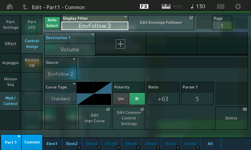
From the main Performance (Home) screen: – Press [EDIT]. – Press [PART SELECT 1/1] – Touch “MOD/CONTROL”. – Touch “CONTROL ASSIGN”. – Touch the DISPLAY FILTER box to open the LIST VIEW. – Use the DATA WHEEL to scroll down to “EnvFollow 2” (which means that PART 2 will be referenced as the SOURCE). Here you can see how the VOLUME is being controlled:
In this example the Dance pad is shaped by the rhythm of the synth arpeggio of Part 2. Selecting the Source “Envelope Follower 2” and the Destination common “Volume” means, that the output of Part 2 modulates the Volume of Part 1. Temporarily reduce the Ratio to 0 – this will remove the influence of Part 2 on Part 1 – you will hear the normal steady sound of the pad sound. As you increase the Ratio toward +63, you hear the increased influence of Part 2 on Part 1.
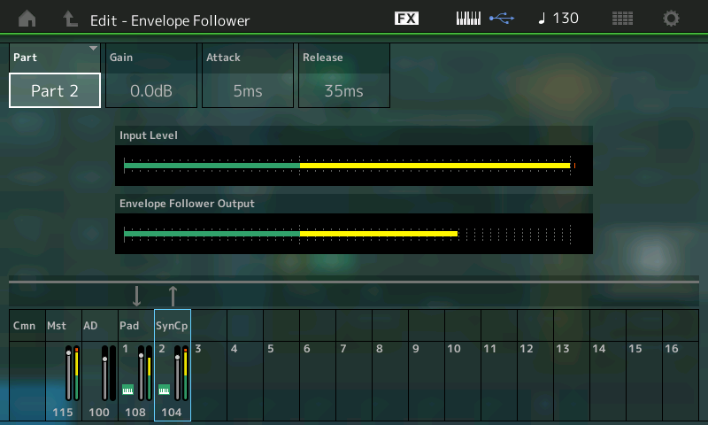
Helpful to understand the routing will be to navigate to the EFFECT itself. In the screenshot above you can see a box next to the DISPLAY FILTER > EnvFollow 2 that is a shortcut box “Edit Envelope Follower” – touch this to be taken directly to the Envelope Follower:
In the screenshot above: PART 2 is selected. It is identified as the SOURCE; the bottom of the screen shows which Parts are feeding into the Envelope Follower as SOURCES to create the “envelope” and which are set to “follow”. From this it is clear that Part 2 (SynCp) is the source, and Part 1 (Pad) is the “follower”. You have GAIN, ATTACK and RELEASE – to help “shape” the envelope. Experiment by changing the Attack and Release to hear the effect on the results. Gain simply increases the audio output of the source energy.
IMPORTANT NOTE: It should be mentioned here that the screenshot above allows you to Edit the GAIN, ATTACK and RELEASE of the item that you have selected as the ENV FOLLOWER source. You do not *select* the SOURCE on this screen. The SOURCE is selected back on the PART CONTROL ASSIGN screen. So when you change the “PART” on this screen, you are simply looking at (viewing) this PART’s meter – its contribution to the mix. Above, we are looking at the INPUT LEVEL of PART 2, we are also looking at the Envelope Follower Output Level; Changing the GAIN, ATTACK and RELEASE of PART 2 will influence the sonic result. By selecting another PART you can see its audio level. By selecting PART 1, the meters will show what the reaction of PART 1 is – it is responding to the shape created by PART 2.
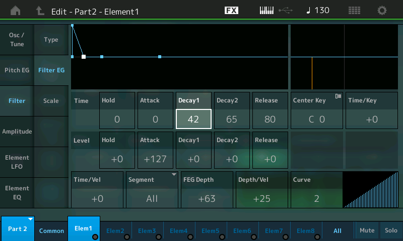
An important chance for changing the character of the modulation further, exist by using the filter envelope of Part 2 (Element 1). Especially the short filter decay (Decay1Time) is very important for the conciseness for the shape of the modulated Pad sound. If you increase the Decay Time the intensity rhythmic modulation will be reduced more and more.
The Envelope Follower’s impact can be easily demonstrated in this example by navigating to the Filter EG:
– From the main PERFORMANCE (Home) screen. – Press [EDIT]. – Press [PART SELECT 2/2] to view PART 2 parameters. – Touch “1” on the bottom line of the screen to view Element 1 settings. – Touch “Filter”. – Touch “Filter EG”. – You can see you are editing PART 2 – Element 1.
Highlight the TIME parameter “Decay1” in the screen (shown).
Increase the value above 42; then decrease it again to hear what the Envelope Follower is doing. It allows you to shape the overall sound.
The same chance for changing the character of the sound exist in the Amplitude Envelope Generator of PART 2 (Element 1). Both the Filter EG and Amplitude EG must be seen as influencing the sound output over time. Filter EG often depends on the Amplitude EG, because if the AEG does not allow for sound to happen, movement in the filter is meaningless. Therefore, if the AEG is not allowing any sound to occur, you will not be able to tell what the Filter is doing – they work together! (Plain Talk: the AEG allows for volume change, if there is no volume allowed, you will not be able to hear filter movement. Simple as that!)
Of course, the sound and/or device you choose to generate the source signal will have a great deal of influence of the result.
Extra Credit: Volume (amplitude) is a very typical use for the Envelope Follower, because we are using the loudness of the source to control the loudness of the target; but do not limit your thinking to the obvious or typical. This happnes to be the best way to understand what this tool does, but be sure to use your imagination and do not be afraid to ask “I wonder what will happen…” This is part of the joy of synthesis. Try “Element Pan” instead of VOLUME as a destination for the Envelope Follower. Now instead of changing the volume of the target you can have that audio burst create a movement in position in the mix – get out your headphones as you can send sounds swirling off into the atmosphere. As we dive deeper you will have more of the MONTAGE tools under your belt and with knowledge of what they can do, you will find an endless source of inspiration and things to try. Things do not all have to happen in a typical pulsating rhythmic way, you can create your own custom CONTROL motions over entire sections of music. You can offset the timing, extend when and where and how things occur. We can only open the door, let you peek down the long infinite hallway – it is for you to explore and create the music.
If you have any questions or comments about this article, please join us to discuss them on the Forum here.
The video below is a great accompaniment to this article. Check it out:
Background and Theory
Before we recall and look at the example Performance, lets take a moment to get some new terminology clear. While the concept of a sequence is clear to most of us, what actually is a “Motion Sequence” really? We think of Notes as being the things recorded to a sequence. Similar to how when someone mentions “arpeggiator”, it is the Noted arpeggio Type that we think of first. In the Motif series you could, however, select arpeggios that where controller messages instead of notes. These control arps would apply control changes to your direct playing. They might rhythmically adjust volume or pan position, some added pitch bends, some made changes to filter cutoff and/or resonance. This is a good background for gaining an understanding of what Motion Sequences are like in MONTAGE
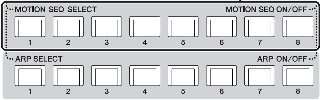
They are not Notes, but are automation for parameter controls – what exactly you patch them to do is a part of the creative use of this feature. How you use this is wide open. The comparison to Arpeggios is very on-point. There are 8 Arps and 8 Motion Sequences accessible via the bottom two rows of front panel buttons.
They can be paired and recalled in tandem; they can be assigned, in any order, to one of the eight SCENE buttons. [SHIFT] + [SCENE 1-8] will register selected Motion Sequence and Arpeggio to a [SCENE] button.
KEY THINGS TO KNOW Please take a moment to read through pages 78-84 in Reference Manual (PDF) to familiarize yourself with the Motion Sequencer parameters:
– A MOTION SEQUENCE is a series of up to 16 steps. It can be as short as 1 step and 16 steps at maximum. – Each Step has an amplitude setting and can be extremely complex. – A MOTION SEQUENCE can be set to Loop, or play when Triggered (like an arp). – A MOTION SEQUENCE can be be adjusted as to timing, intensity, feel (like an arp) via MS FX. – You can assign up to eight desired Motion Sequence types for any one LANE. – You can also set up to four LANES for one Part. A LANE is a pathway to a specific parameter or multiple parameter destinations. Up to eight LANES can be used at the same time for the entire Performance – simultaneously.
You can construct these Sequences manually or select from a variety of preset Sequences. They can be real time adjusted, shaped, and interacted with as they happen. The shapes and nature of these Sequence steps is wildly and amazingly deeply programmable. Sequences can be set to loop, or they can be triggered manually as “one shot” phrases, or retriggered at “each key-on”, or just play from the very first key-on, etc., etc., etc. They can be sync’d to tempo, they can be set to divide or multiply the current tempo (stretching out to some 64 measures; they can follow the arpeggiator and start when it does, they can run freely. Tempo and timing offsets can be applied (like PLAY FX in the XF) allowing you great flexibility in how they “feel” when applied to the synth. You can sharpen and/or amplify their influence on the target.
You can use these in rhythmic ways – the obvious and typical use would be a very rhythmic movement of the cutoff frequency, or the rhythmic pulsing when assigned to volume or pan position. The assignments go way beyond these typical uses – they can manipulate a wide palette of parameters, even parameters that control other parameters. And since they can reference tempo, or even be manually triggered, you can use this feature to accomplish all kinds of musically related automation. Ability for MONTAGE to link with and derive tempo from external devices means that it can play “tempo/measure aware” of its surroundings. More on this in future articles. You can use it to add a single change event that occurs at set intervals – many times events are set to occur at 4, 8, 12 or more measure – using the Unit Multiply setting you can change how your Sequence references the Tempo. Unit Multiply = 100% would make sixteen steps equivalent to 1 measure. You can expand the reference out to 6400%.
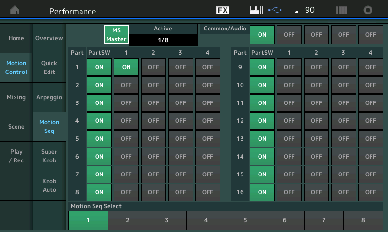
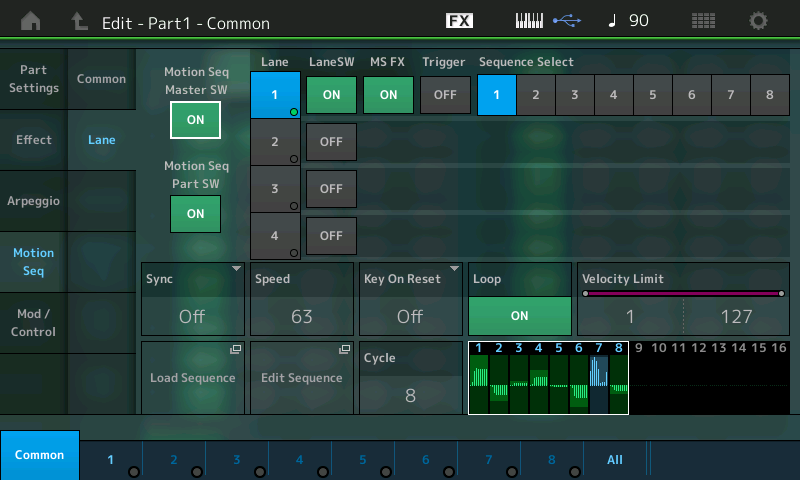
PERFORMANCE 15: Motion Sequence 1 MONTAGE: from the PERFORMANCE (HOME) screen touch “MOTION CONTROL” > “MOTION SEQ”. Here you will find the “MS MASTER” switch and an overview of the various PART SWITCHES. (Please note: The Live Set that is used in the Mastering MONTAGE series is located here.)
– The PART SWITCH for each of the 16 Synth Parts defaults to ON. You must additionally activate a LANE for anything to happen. – The MS MASTER (Motion Sequence Master) Switch is repeated in this screen and this operates the front panel button’s On/Off function. (The Master ARP ON/OFF and MS ON/OFF are adjacent to each other on left front panel next to the SCENE buttons).
In the screenshot above, you can see the four Lanes available per PART. Total – there are 64 LANE switches. – the “ACTIVE” box counts how many of the eight simultaneous LANE switches are currently active. Only PART 1 has a Lane Switch active in the above shot, so 1 of 8 is shown as Active, “1/8”.
Actually, there can be 8+1 Lanes active. The “+1” refers to the dedicated Motion Sequence available for automating the Super Knob movement (covered separately).
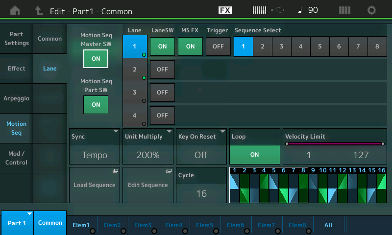
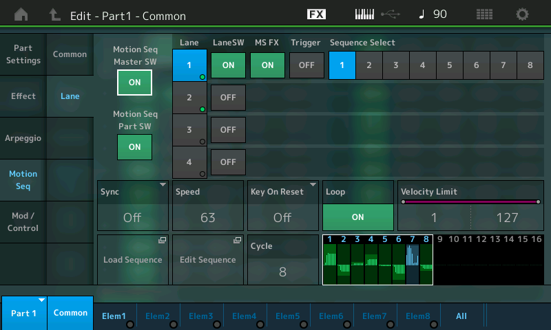
When you drop into the PART level of editing for MOTION SEQ > LANE you see that in this example, only LANE 1 is active (blue LANE 1). MS FX is ON, which allows timing offsets to be applied. We are viewing Sequence #1 of 8 possible sequences: – Press [EDIT]. – Press [PART SELECT 1/1] to view PART 1 parameters. – Touch “Motion Seq” > “Lane”:
Shown (above) “Edit – PART 1 – COMMON > “Motion Seq” > “Lane” screen. Here you will find the Master Switch for the Motion Sequencer (repeated) and the PART Switch, as well (repeated) for convenience. Notice the Shortcut Boxes to ‘LOAD SEQUENCE’ and to ‘EDIT SEQUENCE’.
You have to make the Destination assignments in the Part “Mod/Control” box: without a parameter Destination, the Motion Sequence does nothing. It is controller data, that needs a Destination to manifest its influence. This is a very important concept to understand. Say the Motion Sequence is a series of values that decrease and then increase, until you assign that to a parameter (Destination) it doesn’t mean any thing. If assigned to a LPF’s cutoff frequency then you will hear it manifest itself changing the timbre of the synth on the notes that you play:
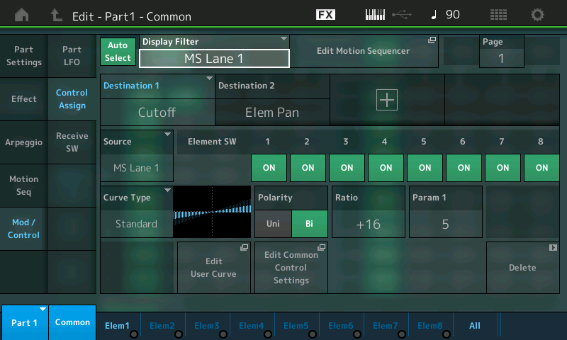
– Touch “Mod/Control” > “Control Assign” – The DISPLAY FILTER is highlighted and “MS LANE 1” is selected. You can see the Destination 1 = Cutoff, and Destination 2 = Elem Pan:
We start here with two very obvious Destinations – easy to hear and recognize. Increase the Ratio to get a sense of what is being changed. Polarity is set independently for each to bipolar – we are offsetting the cutoff frequency above and below a normal setting; with pan we are moving right and left from a center position. Switch between Destination 1 and 2, and adjust the Ratio amount, observe (hear) the influence.
Important to know: In this example the used Control Sets are both routed: – Source: MS Lane 1 > Cutoff. – Source: MS Lane 1 > Element Pan. As you can see it is possible to assign more than one parameter to a Lane. You simply touch the “+” ADD icon to add a new Source/Destination setup. The significance of being able to select as the SOURCE “MS Lane” means that you can group your automation shapes – In a Part with multiple Elements, a Lane could be assigned to influence Elements 1-4 to create coordinated movement in both filter cutoff and pan position, while a second MS Lane could be used to automate contrary movement in Elements 5-8, or move at slightly different rates and directions. It’s a synthesizer!
Touch the box next to the DISPLAY FILTER called “Edit Motion Sequencer” to take the shortcut to the currently selected Motion Sequence. For this example we only need Lane 1, which uses these settings:
As mentioned before, each Part includes eight Motion Sequences, 1 – 8, which can be selected for playing by the MOTION SEQ SELECT buttons on the panel when performing, or the SEQUENCE SELECT buttons, while here on this EDIT screen.
If you, for example, switch to SEQUENCE SELECT number 2, you will receive a new set of 4 lanes with completely different Motion Seq steps, Curves and other parameters. It’s huge.
But please remember the limitation of maximum 8 Lanes, simultaneously. Later we’ll take a look at a PERFORMANCE that uses all 8 Lanes of assignment.
Basically, you will not always need several Lanes for a Motion Seq, because you can assign more than one parameter to a Lane. But it can be extremely interesting to use different Lanes for specific control assignments. Using the UNIT MULTIPLY feature, you can space events out over entire sections of music. If you think of the 16 Steps as one measure, this equates to UNIT MULTIPLY of 100%. You can expand the time out to 6400% (64 measures). Your mileage will vary.
The ramifications of assigning more than one parameter to a Lane are that it will follow the same control movement, which, musically speaking, can be just fine. The degree of response is individually programmable. In our example, both Cutoff and Element Pan share the same Lane, but each has its own set of “depth” parameters that determine how deeply it gets applied. When making your own programs you will need to determine which parameters need to be controlled with their own independent movement, and which can share.
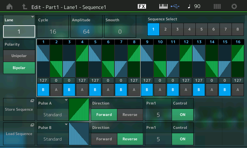
You can edit the steps of the Lane to an extremely deep degree.
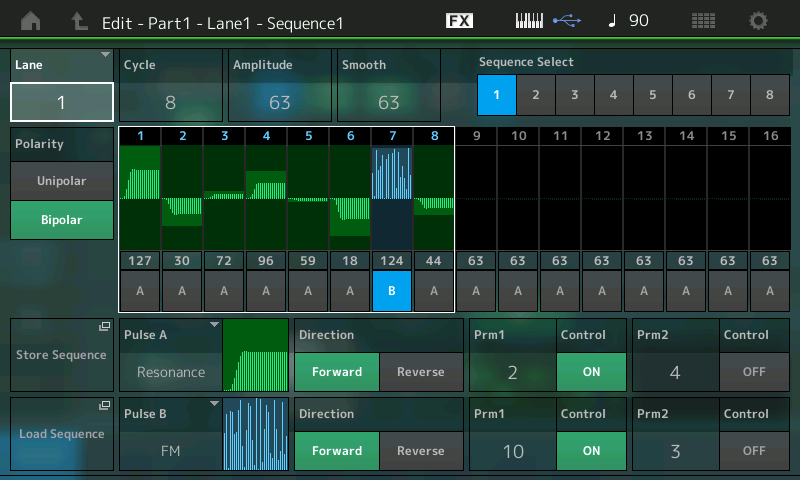
Notice that the Steps are divided into two sets of eight on the screen, 1-8 and 9-16. (A white box in the screenshot above outlines STEPS 1-8). You can set the CYCLE value to any number of steps, for odd time signatures, etc. They are grouped in sets of 8 so that you can use the eight Faders and the eight Switches below them to adjust the Amplitude and select the shape Pulse Type A or B in realtime, respectively. This hands-on method will allow you to intuitively set accents or swap Pulse Types to create different movements. Rather than step-editing by accessing one Amplitude value in the screen at a time, you can quickly create Amplitude ‘shapes’ using the Faders. Then you can dial it in, by accessing the individual values. Try it. Move the Faders to adjust the amplitude of the corresponding Step and touch the blue SCENE buttons to switch it from Pulse A to Pulse B (blue).
Beside setting the values of the steps, the most important thing is to set the Curves and determine their Shape (prm1/prm2) – separately for the Normal and Accent steps.
You can select one of the 18 PRESET Curve types. Each Curve Bank A/B includes a specific number of curves with different shapes.
For example, we see Resonance is shown for Pulse A, with the Prm (parameter) numbers 2 and 4; Prm1 = 2 and Prm2 = 4
You can see what they are talking about by adjusting: Prm1/Prm2 – which help shape the segment. When the “SMOOTH” parameter is turned down (lower the value) , you will hear more of a radical impact. “Smooth” does just what it says, it rounds off the results – so you can make sharp abrupt changes or rolling smooth changes.
The two numbers (PRM1/2) are used for distinguishing the different shapes of a Curve type. The first number stands for coarse, the second number for fine distinctions.
18 Preset Curves: Standard, Sigmoid, Threshold, Bell, Dogleg, FM, AM, M, Discrete Saw, Smooth Saw, Triangle, Square, Trapezoid, Tilt Sine, Bounce, Resonance, Sequence, and Hold
Example: In case of the Curve type Resonance there are totally 30 possible Curves Forward and 30 possible Curves Reverse. Prm1 can be set to one of six values: 0 through 5 Prm2 can be set to pme of five values: 0 through 4
On the Lane 1 line in the screen you can see the Lane Switch and the MS FX Switch. Then the “Trigger” (currently Off) allows you to manually trigger the MS to play as a one time event. You do so by using the dedicated [Motion Sequence Trigger] button located near your Wheels. Much like Arpeggio Phrases, there are a variety of ways to use a Motion Sequence. Think beyond just “looping” (Cycle) events.
The parameter Direction, (found in the MS Edit area) selects between forward and reverse.
If you want to realize separate Steps and Curve settings for specific parameters you can use more than one Lane. In this case you have to make different control set (Source/Destination) routing for each parameter.
EXTRA CREDIT
Try Loading some of the PRESET CURVES: – Touch the shortcut box “Load Sequence”. – Find the PRESET Folder. – Touch it to open it and select “BIG TRIANGE 4”. – Below I have set SYNC = TEMPO. – UNIT MULTIPLY = 200%. – And the CYCLE = 16 steps.
Touch the “Edit Sequence” box to drop into detailed editing of the Sequence:
Press [EXIT] to return to your “Mod/Control” > “Control Assign” screen and experiment with the parameters. You can clearly see/hear the Filter follow this movement and the Pan also follows this same movement. Visually you can picture the filter closing and opening following this Big Triangle as it makes four trips per Cycle. If you assign it to Pan, then you will hear it manifest itself by moving the signal from hard right toward center and then to hard left. Play with + (positive) and – (negative) RATIO values to hear the change in application..
Just because a Part can utilize four Lanes does not mean you will apply that many to a Part. A single Lane could be simultaneously changing multiple parameters. In the example we see it change filter cutoff and panning. Panning the Element might be enough. Certainly panning, and volume, and cutoff and LFO speed might be overkill for a single Part, but you could use all four pathways to assign control on this one Part. That would leave you just four other pathways (Lanes) you could establish elsewhere for this Performance! A quick study of how the programmer’s of Montage use Motion Sequences (MS) will give you a better idea of how to apply this tool. We’ll give you a list of Performances to look at in the Extra Credit area at the end of this article.
The Super Knob has its own dedicated Motion Sequence which can be used to automate the parameters assigned to it. This is in addition to the 8 Motion Sequences available to the individual synth Parts.
The Sync and Tempo settings are complex. Sync settings: Off – not synchronized Tempo – references Montage clock settings Beat – references internal or external tempo starts at beat timing Arp – synchronized to internal/external tempo starts when triggered with Arp phrases
“Speed” setting used only when SYNC = Off.
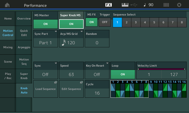
Super Knob Motion Sequence The Super Knob Motion Sequence works basically same way as the Part Motion Sequence. But assignments in the Controller Box are not needed, because it is simply an automation of the Super Knob movement. From the HOME screen: – Touch “Motion Control” in the first column, “Knob Auto” in the second column – Set the SUPER KNOB MS = ON (shown below):
If you want to control the complete range of the Super Knob it is needed to set Polarity to Unipolar and Amplitude to 127. Touch the “EDIT SEQUENCE” box and work with the POLARITY.
Study PERFORMANCE: “Wax and Wane”.
PERFORMANCES To STUDY: Motion Sequence
“Pad Pulsations” – This Performance utilizes the maximum 8 Lanes of Motion Sequence. And has 8 different Motion Sequences. Explore. “Motion Filters AF” – Try different Filter automation via the SCENE buttons. “Pond Ripples” – This Performance uses the Super Knob Auto Play. “Bit Performer” – This is an example of the Motion Sequence placed on the button [Motion Seq Trigger].
If you have any questions or comments about this article, please join us to discuss them on the Forum here.


 On the Lane 1 line in the screen you can see the Lane Switch and the MS FX Switch. Then the “Trigger” (currently Off) allows you to manually trigger the MS to play as a one time event. You do so by using the dedicated [Motion Sequence Trigger] button located near your Wheels. Much like Arpeggio Phrases, there are a variety of ways to use a Motion Sequence. Think beyond just “looping” (Cycle) events.