The focus of this article will be to introduce you to the XF effects. “A picture is worth a thousand words”, some great mind said. Please refer to the XF Reference Manual pages 23-24 for the full graphic story on the Effects routing in the XF for VOICE mode, PERFORMANCE mode and for MULTI modes. This makes it very clear where the Effects blocks are and when they are available via a block diagram flow chart. We will try and make clear how this impacts you using the XF to its fullest.
In VOICE mode:
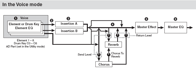
There are up to 8 Elements (Element – is a multi-sampled instrument or part of and instrument sound) in a normal XF Voice. They can be individually assigned to the INSERTION EFFECT block, which is a dual block (Insertion A and Insertion B) that can be routed in “series” (series – is one after the other) or in “parallel” (parallel – is one besides the other). See the routing as A-to-B, B-to-A or parallel.
Each Element has a signal path to the Insertion block – they can be routed to “ins A” to “ins B” or to neither (“thru”). The two System Effects (Reverb and Chorus) each have their own send levels for the entire Voice (that is, all the Elements together). And there is an independent RETURN level and PAN position control for each System effect – mixing the signal back into the main flow; and a PAN position control. Next, the entire signal then goes on through the Master EFFECT, the Master EQ (a 5-band EQ) then on to the main stereo output.
An important thing to understand about these VOICE mode effects is that the Insertion Effect assignment can be recalled for up to 8 of the 16 Parts when a VOICE is used in a multi-timbral setup in MULTI mode and all 4 Parts of a PERFORMANCE plus the A/D INPUT can each recall their own two Insertion Effects …more on this point in a minute. There is one A/D INPUT PART for all of Voice mode – it can be routed to its own two Insertion Effects.
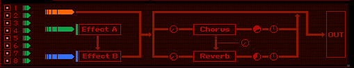
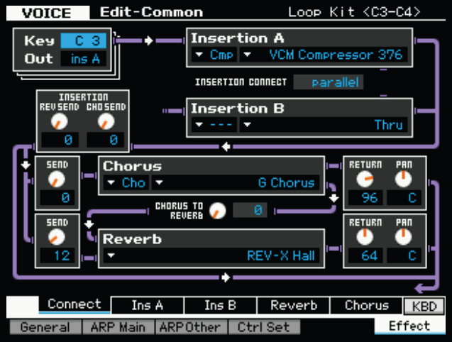
What this means in simple terms is: An XF Voice can be very complex in terms of how it deals with Effects. Each component that makes up a Voice can be routed to one or the other or both or neither of the INSERTION processors. In the flowchart from the Motif XF Editor (shown above) there are 8 Elements on the left. They are all routed (green) to Effect A. Effect A is in “series” with Effect B – this means the signal of each Element goes to Insert Effect A first, then to Insert Effect B… before it travels to the System Effects. You see a rotary control (Send Level) for the entire signal going to each the Chorus effect box and one to the Reverb effect block. There is also a rotary knob between the Chorus and Reverb blocks. After these blocks there is a RETURN Level and Pan position control for the effects, then on the OUTPUT. In the column at left is the same routing situation from the manual.
The INSERT EFFECTS are the effects that you can control in real time – by assigning important parameters to physical controllers like your Mod Wheel, Foot Pedals, Assignable Knobs or Assignable Function buttons, etc. The INSERTION Effect often gives the Voice its personality. The Rotary Speaker for a B3 sound, the soundboard Damper Resonance for the piano, and the Overdrive Distortion for the electric guitar are all examples of effects that give a sound its identity/personality. They are intimately involved with the Voice itself. The soundboard on a piano is like its own internal reverberation, while the Reverb processor can be thought of as the external environment.
The SYSTEM EFFECTS (Chorus and Reverb) are overall effects – they are shared by all the Elements together. They provide the outer environment for the sound. That is, the SYSTEM EFFECTS are very much like the room acoustics. Reverb is the size and shape of the room in which the instrument is played. The Chorus processor can be thought of as a “time delay” effect. Its principal function is from extremely short time delays (Flanging and Chorusing) to long multiple repeat delays (like Echoes). Time Delay is important to the perception of a sound – it gives the listener a sense of distance from the sound source.
In PERFORM mode:
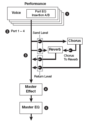
There can be up to 4 Voices plus an A/D INPUT in a Performance. The DUAL INSERTION EFFECTS are available for all four synth Parts of the Performance and for the A/D Input. That is, the synth Voices in a Performance can recall their original Dual Insertion Effect routing and control while in a Performance. What actually happens is you are activating the Dual Insertion effects that are programmed in at Voice level. Insertion Effects are applied at the VOICE Edit level.
What this means: An organ sound that has a Rotary Speaker and Amp Simulator effect back in Voice mode will automatically recall these (personality) effects when you place it in a PART of a PERFORMANCE. The guitar sound that has an Overdrive Distortion and Wah-Wah effect back in Voice mode will automatically recall these effects when you place it in a PART of a PERFORMANCE. The Full Concert Grand piano will automatically bring along its Damper Resonance – because INSERTION EFFECTS can be considered a part of the VOICE. Of course, any assigned controllers are also automatically recalled as well.
If you think of these personality effects (Insertion Effects) as the personal property of the Voice, it may become clear. The guitar player sitting a home in his apartment (VOICE mode) connects (inserts) his guitar to an overdrive stomp box and a wah-wah pedal… these are his personal effects… when he joins the band at the rehearsal hall (Performance mode) he can bring these two personal (insert) effects with him.
Each Voice in a Performance is called a ‘PART’. And each Part has an individual send level to the System Effects so that you can control how much is applied individually. There is a return level from each System effects. The total signal is delivered to the Master EFFECT, then to the Master EQ and then on to the stereo outputs.
The System Effects belong to the rehearsal hall… they are, after all, the room acoustics of this new location. All the instruments will share the same room acoustics, however, you have an individual SEND amount control to position each player within that room.
We mentioned that the A/D INPUT PART can also use a pair of Insertion Effects. And this is very powerful because for each PERFORMANCE you can customize the microphone channel. The Mic settings are global for Voice mode – this means the setup you create for the A/D Input while in Voice mode is a setup that will be for all of Voice mode. But the setup you create for PERFORMANCE mode can be setup on per PERFORMANCE basis. This makes sense because the purpose of PERFORMANCE mode is for you to put together the things you would want to recall while performing. You plan ahead, decide on this particular number I want the microphone to have a compressor, a tempo delay, reverb and EQ, and on this next particular song, I don’t need the microphone at all. You can setup to have the microphone ON or OFF, with particular effects or none… it is entirely your call. So rather than trying to readjust the microphone setting on-the-fly a PERFORMANCE is a place to store your customized setting for you microphone on a per program basis.
In MIXING mode:
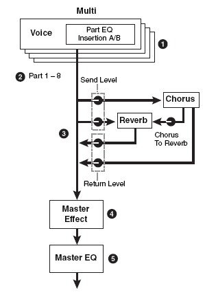
The Tone Generator block can have a total of up to 16 synth Parts, plus an A/D Input Part. The DUAL INSERTION EFFECT can be activated on any eight Parts from the internal XF (1-16) or the A/D PART. Each Part will have an individual send to the System effects. And finally, all signal goes through the Master EFFECT, the Master EQ and then on to the main stereo outputs.
We will mention this here because it is important to understand that while both PERFORMANCES and MULTIS deal with VOICES placed in PARTS, the difference between a PERFORMANCE and a SONG/PATTERN MIXING is that a PERFORMANCE allows you to play all four synth Voices simultaneously. You are addressing them on a single MIDI communication channel. A Mixing/Multi gets its name because you are placing the Voice in PARTS and each PART could be on a different MIDI channel. You typically can only transmit on one MIDI channel at a time, so Multi mode is typically used with an external sequencer or the internal playback sequencer.
You can see how a PERFORMANCE can be copied to a MIXING – because all you would need to do is address the four synth Voices on the same basic MIDI channel to accomplish what you do in PERFORMANCE mode. A MIXING exists so that you can place sounds on different MIDI channels, as necessary to accomplish your goal. Conveniently the PART SELECT buttons, [1]-[16] allow you to transmit to a particular PART. So an alternate use for MIXING mode is to place your favorite Voices in the PARTS of a MIXING and then you can easily, quickly and without sound interruption, select between them.
For example, say on a gig, you need to play strings on the introduction of the song and you need to hold the last chord of the string intro, switch to piano and begin the groove section with a two-fisted piano riff. Then later you need to switch to a lead sound, then back to piano and finally to strings again. You could place these sounds in a MIXING and easily accomplish this by pressing the PART SELECT button associated with where you placed these Voices.
And with a little imagination you can see that this can be used to call up complex splits and layers as well – because PARTS of a MIXING can be segregated to specific regions of the keyboard, can be stacked on the same MIDI channel where necessary. So your imagination is your limitation.
The reason you can switch between PARTS without sonically interrupting the sound (i.e., the strings sound in PART 1 can be held with your fingers or with the sustain pedal while you switch to the piano sound in PART 2) because you do not have to change or interrupt the intimate routing of the effect processing. It is because the XF effects are so very powerful that you cannot switch from VOICE to VOICE in Voice mode without interruption of sound. If all you have is external (System Effects) it would be simple – as the routing would therefore be simple.
This use of the MIXING is very powerful for those of you on stage who need several sounds within one song and are trying to figure out how to accomplish this goal. We discuss it here in the article on Effects because it is very much related to the Effect processing capabilities.
Since 8 of the PARTS can recall their dual Insertion Effects from Voice mode, you can customize your sounds as you require. A little bit of planning and programming should not scare you off – you purchased an extremely programmable synthesizer and you are expected to customize things to your liking. There are 128 MIXING for you to program. The 64 SONG MIXING and 64 PATTERN MIXING. Please feel free to customize them to your own use.
Background
The algorithms (a fancy word for ‘recipe’ or specific arrangement) in the XF Effects are deep. Please refer to the DATA LIST booklet to see the individual parameters and effect types. On page 95-104 of the DATA LIST you will see a list of the different Effect Categories and Effect Names. It will list the parameters available in a convenient form to see them all and the ranges of control. This is worth a look. The TABLE Number heading is for those that need to know the exact value of each setting – refer to the charts on pages 108-115 for exact values for each parameter setting. Basically settings are made to taste (by ear). However, knowing what is subjective and what is objective is what separates a bogus mix from a brilliant mix.
So much of working with sound is subjective, meaning it is up to you, but some of it is very objective, meaning there actually is a right and wrong. It’s true. Knowing the difference between these two concepts is the key to greatness in the audio business. For example, when routing signal to an effect, do you return more than you send or send more than you return?
Gain staging is the objective part of audio. Making sure that you work on the side of SIGNAL when dealing with the SIGNAL-to-NOISE ratio. The rule of thumb: Send up to the limit of clean audio and return just enough to taste. However, often your SEND amount determines how much effect you are going to get. So you also have to consider balancing how much SEND compared to another channel. This is very true in situations where sounds are going to share an effect (like the System Effects). So there are no cut and dry rules – you have to find the balance between the objective and the subjective.
If, however, you are sending signal to an effect processor that you have configured as an EQ, how much signal do you send? This is not subjective, there is a right and wrong. Send all the signal through the EQ. If you were to return dry signal from certain routing scenarios you can cause phase cancellation – a situation where you will be adversely affecting the signals integrity. Knowing what you are doing with effects can mean confident utilization with stunning results. Just experimenting willy-nilly can lead to bogus results. Of course, you could eventually wind up with something useable but the old saying: “Knowledge is power” does apply here. In most instances the XF will not let you get into too much trouble – sometimes you are prevented from controlling certain things because it would be illogical or lead to bogus results …those decisions are made by the designers. For example, you will see where a subjective return is allowable: a DRY/WET balance parameter. This is so that you can mix your amount of effect return, but from a device like an EQ there is no DRY/WET balance control parameter, because the design will not let you make that “mistake”. This is a good thing.
As you will learn, not all parameters are available for real time control – again, a design decision is made to prevent unfortunate illogical assignments that would cause sonic problems.
The Processors
We often get asked about the quality of the Effect processing and it should be stated that the introduction of the VCM and some of the other new effect types found in the XF-series, has elevated the quality of processing found in keyboard and rack mounted synthesizers to a very high level. These effects have trickled down from the very high-end Yamaha digital consoles that are on tour with most every major act. Undoubtedly if you have attended any concerts in the last 10-15 years you have heard Yamaha effect processing in action.
The Effect processors are divided into SYSTEM Effects (Reverb and Chorus processors); INSERTION Effects (applied within the Voice architecture); MASTER Effects (applied overall just before the final output).
The SYSTEM REVERB processor has 12 main algorithms available and 50 Presets to use as starting points. When working with a reverb algorithm you can select by size environment: REV-X HALL, R3 HALL, SPX HALL, REV-X ROOM, R3 ROOM, SPX ROOM, R3 PLATE, SPX STAGE, SPACE SIMULATOR, HD HALL, HD ROOM, HD PLATE. Then from there you can tweak it to match your specific needs. In general, you will not know what is sonically possible until you experiment with the effects. Resist the urge to do nothing. It takes no effort to accept the preset as it is – you may find by changing a few things you can get exactly what you like.
Yamaha was the first company to introduce DSP effects that were based on the actual dimensions of the great concert halls of the world. A “HALL” is typically a large concert environment. The REV-X is the most recent development in a long line of Yamaha reverberation chamber algorithms and is the same effect found in the SPX2000 processor and in the high-end digital touring consoles from Yamaha. The Pro R3 was one of the first high-resolution digital studio reverbs and enjoys a stellar reputation in the field. The Yamaha SPX introduced the project studio digital reverb back in the 1980’s.
Reverb Types that are “ROOMS” bring a definite size factor component to the space. A “STAGE” is usually a loud reverberant environment. A “PLATE” is a brilliant emulation of the old 10-foot boxes that used to contain these reverb chambers that used a transducer (driver) at one end and second transducer (microphone) at the other…in between was a large aluminum plate. You sent signal from the mixing board’s aux sends and returned up to a maximum of 5 seconds of cool reverb. This was the standard for drums and percussion “back-in-the-day”. The SPACE SIMULATOR will help you design your own environment and can teach you about how the other presets where made. It allows you set width-height-depth of the walls and the ‘wall vary’ lets you set the reflective texture of the surface from rug to steel. A rug absorbs sound, while the steel would be highly reflective. Under the SPACE SIMULATOR you will find several presets that will give you an idea of just what type of spaces you can simulate: Tunnel, Basement, Canyon, White Room, Live Room, and 3 Walls…
When you are thinking about these you must imagine how each will sound and why. A tunnel, for example, is long and narrow with reverberant surface walls; while a basement also has a low ceiling but probably not much reflection of sound. A canyon you can picture has no ceiling so it is a wide-open space with a long reflection and bounce back. The “Space Simulator” is a starting point – you configure the space – presets are simply starting point…
Also important in working with reverb is an understanding of how it works in the real world. In most listening situations you are hearing a certain amount of signal, directly from the sound source, while the rest of the signal bounces off the environment you are standing in. If, for example, you are 30 feet from the stage you will hear a portion of the sound direct from the stage but most of it will bounce off of the walls, floor and ceiling to arrive at your position. Because we often record and/or amplify musical signal with a technique called “close-miking”, reverb became a necessary evil (if you will). Close-miking allows us to isolate a particular sound from others in the environment but there is a trade off… we lose that sense of distance and environment. To regain some of the distancing we use artificial reverb to do the trick. Recognize that when you put a different amount of reverb on the snare than you do on the flute this does not occur in nature. All the musicians in the same room would naturally have the same reverberant environment with very subtle differences due to positioning in the room. This gets back to the subjective part of the audio business. SO WHAT? You can use effects to taste. There is no rule that says everyone has to have good taste nor do you have to exercise it. However, keeping a reality check (an idea of what would happen in the real world), can only help. No one is saying you cannot create some science-fiction sound environments, of course, you can, just know when you are doing so!
An important parameter in all the reverbs is the INITIAL DELAY this is the time before the reverb receives the signal and can help position the listener near/far from the instrument source. The initial delay in any acoustic environment is the time it takes before the signal reaches a significant boundary. In a large hall it could be several hundred milliseconds before signal bounces off the back wall. Your ear and brain can easily recognize this and it gives you a perception of exactly from where the sound is emanating. The DRY or unaffected signal travels to your ear directly, the reverberation begins some short time after. This can be only a few milliseconds but is plenty of time for the ear/brain to analyze and conclude specifics about the environment. When too many different unnatural reverberations occur, the music becomes confusing and unnatural. If that is what you are going for then this is fine. But if you ever wonder why some mixes are just better than others – a lot of the reason has to do with the subtleties of the mix. And make no mistake the EFFECT processing is a huge part of this.
The HPF (high pass filters) and LPF (low pass filters) found within the Effect algorithms are there to help you shape the reverb signal itself. There is a rule of thumb here: low frequencies reverberate less than high frequencies. Low frequencies tend to hit a surface like a wall and spread out while high frequencies hit a wall and bounce right back into the room. This is why, when you are sitting next door to the party, you only hear the bass through the wall – all the high frequency content ‘reverberates’ and stays in the source room. So use the HPF (high pass filter) to allow the highs to pass through to the reverb and block the lows from reverberating. Reverb on bass just adds MUD. MUD here, is not a subjective term but if it is what you want, go for it (but yuck, it is mud). Low frequencies don’t bounce back they tend to hug the walls and spread out. If you want cutting, punchy bass leave the bass “dry” (without reverb).
The XF Reverb processor features a brand new effect algorithm set based on the heralded Yamaha “Rev-X” technology. “REV-X” is a whole new generation of Yamaha Reverb with the richest reverberation tone and smoothest decay. There are “Hall”, “Room” and “Plate” algorithms. Parameters like ROOM SIZE and DECAY envelope also bring much higher definition and finer nuance. The number of reflective impulses it uses determines reverb quality …the higher the number the more definition and the finer the quality of sound. It is processor intensive – these are very short sound reflections but lots of them to make the sound smooth.
Added with Operating System Firmware update (1.50) are the three High Definition Reverbs: HD HALL, HD ROOM and HD PLATE. Remarkable smooth and silky sounding these high resolution reverberation chambers add the right finishing touch to any project. It would be difficult to describe reverb as warm (it is such an icy affair) but rich and enveloping are terms that come to mind.
The SYSTEM CHORUS processor features time delays from flanging, to chorusing/phasing and on out to multiple repeats and echoes. We are talking much larger than the distance between reverb reflections because these can be heard as separate events. The CHORUS processor is more than just chorus and delay effect types. You even get additional Reverb algorithms for maximum flexibility when mixing. There are also tempo control delays that can be synchronized to the BPM of the music.
There are six different main categories in the CHORUS processor:
Reverbs (3 types) – 12 presets
Delays (7 types) – 41 presets
Chorus (5 types) – 28 presets
Flanger (3 Types) – 13 presets
Phaser (3 types) – 37 presets
Miscellaneous (1) – 5 presets
A Flanger is a time delay effect. If two identical signals arrive at your ear-brain, you will not be able to perceive them as two separate signals until one is delayed slightly. Imagine 2 turntables in perfect synchronization playing the same record at exactly the same speed. You would perceive the second one as just making the first signal louder, until you delayed one of them a bit. If one slips 1ms behind the other you will perceive what we call flanging. The actual name comes from two 2-track reel-to-reel tape decks playing the same material. This was used as a real time effect, “back in the day”. You would have 2 identical 2-track decks running in sync (no, there were no protocols to sync them – you pressed the buttons at the same time!!!) The engineer would slow one down by placing his thumb momentarily on the flange (reel holder). The resulting swirling sound is called flanging. And there were no settings, no presets – it was all done by ear. It was a short time later that a Flanger became a rack mount device – and while the original Flanger cost around $1500, it was still a lot cheaper than two 2-track tape recorders!
Any delay between exact sync and 4ms is considered flanging. Delays of 4ms-20ms are considered chorusing and somewhere beyond 30ms the ear-brain starts to perceive two separate events, called doubling or echo. Among the ‘time-delay’ algorithms in the Chorus processor you will find: Cross Delay, Tempo Cross Delay, Cross Delay Mono, Tempo Delay Stereo, Delay L/R, Delay L/C/R, Delay L/R Stereo, G Chorus, 2 Modulator, SPX Chorus, Ensemble Detune, Symphonic, VCM Flanger, Classic Flanger, Tempo Flanger, VCM Phaser Mono, VCM Phaser Stereo, Tempo Phaser, Early Reflection; additionally you will find three SPX Reverbs available in the Chorus processor (very useful when you want to set a lead or section of instruments apart from the rest of your mix), a Hall, Room and Stage reverb.
Phasing is another category of effect – it is where the two signals are basically the same but instead of one being a wave that starts in the upward direction, the second wave starts perhaps in a different direction.
Each of these main algorithms has their own “Presets”. A Preset simply is a starting point. Remember, only you can know what is working for your particular composition. The Presets are provided and they are meant to be tweaked by you. They are “starting points”. Saying you don’t like any of the presets is, well, if you find yourself saying this, go stand in the corner and give yourself a demerit (lol). You are saying that somehow the original programmer did not know what YOU like. You are correct, so DO something about it, learn to tweak the effects!
The INSERTION EFFECT is made up of two identical units (INSERTION A and INSERTION B). The 53 effect types and scores of presets can be the subjects of intense study. We will try and introduce you to some of the more unusual and unique ones in this article. Many of the recipes (algorithms) are repeated in the Insertion Effects simply to allow you more options when processing your mixes. In addition to all the reverbs, delays, echoes, cross delays, tempo delays, etc., you get some that are available nowhere else. Insertion Effects can be considered a part of the Voice itself, and can be assigned real time controllers so that you can manipulate them while performing.
The VCM (Virtual Circuitry Modeling) Effects are revolutionary in that they are recreations constructed by modeling the circuit components (capacitors, resistors) of the classic gear they emulate. The designer then could reconstruct the products by creating virtual circuit boards. The VCM Flanger is a simulation of the classic vintage flanger devices. The VCM Phasers faithfully reproduce the response of the old mono and stereo guitar stomp box of the ’70’s in every detail.
Among the innovative effects from the Yamaha Samplers A4000/5000 are the Lo-Fi, Noisy, Digital Turntable, Auto Synth, Tech Modulation, Isolator, Slice, Talking Modulator, Ring Modulator, Dynamic Ring Modulator and Dynamic Filter.
If you are asking yourself, why would Yamaha provide effects to degrade the sound (Lo-Fi, Noisy) – with the Lo-Fi effect you can actually grunge the sample rate a thousand times to 44.1Hz (talk about low fidelity) – if this is at all curious to you, “step away from the Lo-Fi effect”! It is an acquired taste and specific to some forms of modern electronica.
There is a Multi-band Compressor algorithm that is great for fixing and punching up specific frequency ranges. Multi-band compressors are used to finalize mixes and bring out (punching up) specific frequency bands without raising overall gain.
The Digital Turntable algorithm adds “record surface noise” to your mix. You can program the tone of the noise, the frequency and randomness of the clicks and pops, and you can even program how much dust on the stylus!!!
Slice is also the name of one of the effect algorithms in addition to being a sample edit process. This Slice effect can divide the audio into musical timed packets that it can pan left and right in tempo. You can select a quarter note, eighth note or sixteenth note slice and there are 5 different pan envelopes and some 10 different pan types. This is great for “gated” effects.
The innovative CONTROL DELAY effect is a digital version of the old style tape delay (Echoplex) where you can create wild repeating effects. When using the Control Type = Scratch you can assign a controller to create insane echo effects.
Added with Operating System Firmware update (1.50) are the new Guitar Effect processors including:
US COMBO A simulation of an American combo amp.
JAZZ COMBO A simulation of a famous combo amp.
US HIGH GAIN A simulation of a famous American high gain amp.
BRITISH LEAD A simulation of a famous British stack amp.
MULTI FX A simulation of multiple effect devices for guitar sounds.
SMALL STEREO Stereo distortion effect for guitar sounds.
BRITISH COMBO A simulation of a famous British combo amp.
BRITISH LEGEND A simulation of another famous British legend amp.
Why is it called “Insertion Effect” and what is the difference between it and a “System Effect”?
On an audio console you have a series of channels. Channels carry input or returns from a multi-track (we refer to them as Input Channels or Track Channels depending on their role). Each channel has an on/off button, EQ, a fader, and a set of auxiliary sends. These ‘aux’ sends allow each channel to send a portion of the signal on what is called a bus (a group of wires carrying like signal). That bus can then be connected to an offsite effect processor in a rack. The return comes back to the board and is mixed to the stereo signal. That scenario is an example of what happens in XF with the SYSTEM EFFECTS. That is, when you are in a MULTI, the REVERB, and the CHORUS Effects are arranged so that access is just like the auxiliary sends of a console – each channel (Part) has an individual send amount to the system effects. There is a composite return signal that is mixed to the stereo output.
An Insertion Effect on an audio console is usually accessed via ‘patch points’ (interruption points in the channel’s signal flow) that allow you to reroute all of the channel’s signal via a patch bay through the desired effect or device. You are, literally, inserting a processor on that specific channel alone. This is how the INSERTION EFFECT block works on the XF.
Examples: Typically, when a reverb effect is setup, just a portion of each sound is sent to it. This is the perfect example of what a System effect is about. However, things like rotary speaker (organ) or amp simulator (guitar) are effects that you might want to isolate on a specific channel. Therefore these type effects are usually accessed as an Insertion Effect. One key advantage of the Insertion Effect is that it can be controlled in real time, during the playing performance. Since the Insertion Effects are programmed at the VOICE level you can use the Control Sets (there are 6) to route your physical controllers to manipulate the parameters of the Insertion effect in real time. You can change the speed of the rotary speaker, or you can manipulate the Guitar Amp simulation setting while performing the guitar sound. This type of control is beyond just the send level (you are given access to System Effect send level only from the Voice mode Controller assignment). In the real world, the size of the room does not change (hopefully) so System effects like reverb are pretty much “set it/forget it”. However, changing the speed of the rotary speaker effect is something that you may want to perform during the song.
Just how are you able to control certain parameters in an Insertion Effect? …via MIDI commands, of course. In the hierarchy of modes in the XF VOICE mode is the most important when it comes to programming. This is where Yamaha spent hours and hours developing the sounds you play. The programmer’s assembled the multi-samples into waveforms, and combined the waveforms into the Voice and worked with the envelopes, the response to velocity, the pitch, the tuning, the filters and so on. Each sample in the XF has its own EQ, the meticulous programming goes on for months at a time. Of course part of the arsenal available to the programmers were the Effects.
Take a close look at a Voice and its effect structure:
Notice the Insertion Effect blocks, the System Effects (REVERB/CHORUS), the Master Effect
block and the Master EQ block. Contrast this to the graphic, which shows the blocks during a MIX in Song/Pattern mode. The Dual Insertion Effect is available for any eight XF (PARTS 1-16 or the AD INPUT).
How to understand the routing…
Navigate to the XF Effect connection screen. In VOICE mode, from the main screen this is done as follows:
• Press [F6] EFFECT”
• Press [SF1] CONNECT
In PERFORMANCE and/or SONG/PATTERN MIXING mode:
• Press [EDIT]
• Press [COMMON]
• Press [F6] EFFECT
• Press [SF1] CONNECT
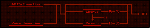
This screen shows you an overview of the connections and the signal flow (follow the routing left to right). It pays to study the diagrams to get a clear understanding of how signal travels. Below you can see this in the Motif XF Editor:
VOICE Mode:
MIXING / PERFORMANCE Mode (Common):
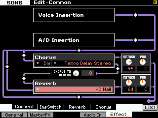
Notice also that both the Mixing and Performance screens do not have rotary send level controls to the Reverb and Chorus. This is because the send level is not a ‘common’ parameter but is on a per PART basis (there will be 16 of them and one for the A/D PART). Each Part will have its own control for the amount of signal sent to the System Effect on the Part Edit level. (Remember the individual SEND amount allows you to position an instrument near or far from the virtual listener’s position). While in Edit, you can select the PART to edit by touching the PART SELECT buttons 1-16 – corresponding to Parts 01-16 and there is a dedicated knob for the MIC (A/D) channel on the front panel.
Notice that between the Chorus processor and the Reverb processor you have a level Send control knob: Chorus-to-Reverb Send. This can be used to create a situation where the System effects are used in “series” (one after the other) rather than in “parallel” (side by side). An example of how this can make a difference is when you select a DELAY as the effect for the Chorus processor and a REV HALL for the Reverb… when parallel routing is selected, you could send a signal independently to the delay and to the reverb. Only the initial note will have reverb, each repeat would be dry. By routing “0” send to the Reverb, but send the signal through the Chorus first, then through the Chorus-to-Reverb send, on to the reverb, you will now have a signal where each repeat of the Delay will have reverb. Quite a different sound…
INSERT SWITCHES in the MIXING Mode
We mentioned that as many as 8 PARTS can simultaneously have the two Insertion Effects active in a SONG/PATTERN MIXING. You can select the A/D INPUT as one of the PARTS with two Insertion Effects – but a maximum of 8 PARTS total.
In PERFORMANCE mode this means that all four synth Voices and the A/D Input can have unique Dual Insertion Effect assignments. But in MIXING mode you will have to select which eight PARTS.
The screen below shows which Parts of a Multi Mix are recalling their Dual Insertion Effect setups. It initially defaults to the first eight Parts. But you can select any PART up to a maximum of eight – including the AD PART.
The Insertion Effects do not appear in the MULTI MIXING CONNECT screen because the Insertion Effects are part of the VOICE mode edit parameters. If you need to radically change an Insertion Effect from the original programming then you will need to create a new USER Voice with your new Insertion Effect edits and STORE it. The XF provides for this with 256 MIX VOICE locations… we will explain below.
What if I want to edit a Voice’s Insertion Effects while I’m working on a MULTI?
You have the ability to edit a Voice directly while still in a SONG/PATTERN MIXING program using the Motif XF Editor.
The XF Editor allows you to drop into full Voice Edit for any Voice while still in the MIXING mode. Simply select the PART by number and click on the EDIT overlay to view and edit all components of the VOICE.
This allows you to edit a Voice and its two Insertion Effects (provided the INSERT SWITCH is active for the PART) while you are using the sequencer so that edits can be done in the context of the music sequence. When you STORE this edited Voice it will automatically replace the Voice in your MIXING in a special “MIX VOICE” bank location.
What this means is the Mix Voice will automatically be restored when you load the file or recall the stored MIXING. The Mix Voice bank is like having an additional storage location for your customized sounds – allowing you to edit a sound for a particular composition without having to overwrite a regular USER Voice location. Each Multi Mix has 16 Mix Voice locations. Due to complexity, Drum Voices cannot be stored in Mix Voice location. And a maximum of 256 Mix Voices can be stored in the Motif XF. You will probably not need to edit every Voice, so having an additional 256 locations to store customized sounds is welcome.
In Voice Edit you have 6 Control Sets that allow you to customize how the available effect parameters are controlled. Choose your assigned MIDI controls wisely, they will be available when the VOICE is used in a MIXING (or a PERFORMANCE).
Master Effects
The Master Effects are “post” everything but the Master EQ. So they are applied to the overall System signal (stereo). These are 8 effect algorithms that you will also find in the Dual Insertion Effects. If you want to apply them to a single sound, you can create a Voice and find the same algorithm among the list of Dual Insertion Effects.
The MASTER EFFECTS are:
• DELAY L,R STEREO
• COMP DISTORTION DELAY
• VCM COMPRESSOR 376
• MULTI BAND COMP
• LO-FI
• RING MODULATOR
• DYNAMIC FILTER
• ISOLATOR
• SLICE
These are sometimes called “DJ”-type effects, for lack of a better term, because like a DJ would, they are applied to the entire recording. DJ’s are either playing back a record or CD that is a finished mix. So the effects that they add are always post, they cannot put a Dynamic Filter on just the snare drum, if you get my meaning, so “DJ-style effects”. These Effects are applied to the entire SYSTEM signal. Don’t be afraid to use your imagination with these Master Effects – some of them are quite radical. Things like putting a Delay on the final hit of the song so that it repeats and fades …or using a frequency Isolator to roll out all the bass for a section of a song, then bringing it back in for dynamic impact …or wacky panning effects with the Slice algorithm where you can pan signal left and right in tempo with the groove. Also on the more normal side, you are given a powerful Multi-band Compressor for pumping up the frequency bands of the final mix. Awesome tools… experiment!!!
Master EQ
Although not technically an effect (EQ is an essential utility for any mixer), the Master EQ is the last process the signal goes through prior to the main outputs.
In Voice mode, the Master EQ is setup and is global for the mode (applies to all Voices). While in Voice mode:
• Press [UTILITY]
• Select “VOICE” > press [ENTER]
• Select “MASTER EQ” > press [ENTER]
Here you find the full 5-band parametric EQ. Parametric means you can select the Frequency, the Gain (increase/decrease) and the Q (or width of the bands). For each VOICE you will find a three band (adjustable Mid-Frequency) Equalizer available via the KNOB CONTROL FUNCTIONS for quick tweaks.
In PERFORMANCE mode or in MULTI mode you can setup the Master EQ on a per program basis
• Press [EDIT]
• Select “COMMON” > press [ENTER]
• Select “EQ” > press [ENTER]
Here you will have access to the 3-band (front panel) EQ and the MASTER EQ
• Select “MASTER EQ” > press [ENTER]
Conclusion and final thoughts
Signal flow is the most important thing to get a handle on when you are seeking a better understanding of audio. This is particularly true when it comes to affective effect processing. The XF uses professional mixing console routing as the basis for how signal flows through the synthesizer. A Voice or Part is like a musician playing an instrument. So imagine a guitar player with a wah-wah pedal, and a combo amp. These are like his Insertion effects… He inserts the guitar into the wah-wah pedal and then to his combo amp. Insertion Effects are controllable in real time by the player – and this is an essential part of performing. That is the guitar Voice in Voice mode.
Now take that player and his rig to a recording studio. This would be the MIXING mode. When you activate the INSERTION SWITCH for the PART containing the Guitar Voice, it is like the player brought along his wah-wah pedal and combo amplifier from home. And they will be able to manipulate them in real time as they perform.
In the studio (MIXING/MULTI) mode they are plugged into the console, the guitar channel has two auxiliary sends. One connects to the studio’s reverberation chamber, the other send can be routed to some sort of delay/chorus/flanger (as may be required by the session).
That is what you have here in the XF. Real time control over personal effects, and a send/return situation with the System Effects.
Now to continue with this analogy, if you route a signal to a direct out on a mixing console, you interrupt the signal in the patchbay… this takes that channel out of the main mix and allows you to route it, in isolation, to some other destination. This interruption removes that channel from the auxiliary sends (the ones feeding the Reverb and the Chorus processors), but you would be doing this interruption precisely because you are going to process the signal in isolation, separately.
When you take a PART of your MIXING program and route it to any of the assignable outputs, it is removed from the main stereo mix, and it no longer is pooled with the others via the aux sends to the studio’s effects.
Routing a channel to a direct output is done when you have something you want to do to it in isolation.
The effect routing in the XF Voice is one of the reasons you can make it sound so good. A Voice can be one or more instruments combined – remember a Voice is made up of as many as 8 Elements. Each Element can be an instrument or a part of an instrument. The VOICE: PRE 1:014(A14) Piano & Strings is an 8 Element Voice where Elements 1-4 make up the piano and Elements 5-8 make up the strings. Because of the intricate routing within the Voice architecture, the four Elements of the piano go to INSERTION A (setup as the VCM EQ 501) while the four Elements of the strings go to INSERTION B (setup as a separate VCM EQ 501) – this is an example of how when setup in parallel each instrument in this combined Voice has its own powerful equalizer. Volume can be controlled separately: The Assign 1 knob controls the volume of the string Elements, while Assign 2 controls the volume of the piano Elements. The Mod Wheel is assigned to increase the Element level of the strings – so it can be used to intensify the strings. The [AF1] button will cause an increase in the reverb Send of all Elements together to the Reverb chamber, while [AF2] will cause a longer release time on the amplitude envelope of all Elements.
You can explore the assignment of controllers and discover how some of the PRESET Voices were programmed by beginning to explore the Motif XF Editor.