Mastering MONTAGE: Getting Started
Assemble the four booklets as PDFs:
Although you are given a paper copy of the Owner’s Manual you should download a PDF of it so that you have the search capabilities afforded reading it on a computer, tablet or notebook device. PDFs will allow you to quickly and easily find information when necessary. Reading a manual, while recommended at some point, should never be handled like you’re reading a novel. It is much more like reading a reference book – where you are looking things up – you use it to connect-the-dots as you gather information while you are experiencing the instrument.
Set them aside, for now, and play the instrument:
Various types of Performances are provided in the Factory Set Preset Banks. It may not always be immediately obvious how to play or interact with them, since they can be quite complicated. Many include advanced programming tricks that may not be immediately decypherable. Please take advantage of the [AUDITION] button: if you have no idea what to play, or how to approach a particular Performance, press [AUDITION] and closely observe the front panel. The Super Knob, Assign Switch buttons, the SCENE buttons etc., will animate in response to the audition data. You can see how different timbres and combinations of instruments settings are accessed. Then try approaching the Performance again with what you’ve learned. The audition function can be extremely helpful in situations where you simply have no clue what the programmer was thinking. Perhaps it is an instrument emulation that has available several articulations that are essential to make it work and sound properly.
Even some single instrument sounds will come to new light in response to the Audition button – what you may think is not such a great sound may be transformed when played with a different approach, a different attack. It can change your mind entirely. For example, you call up a “Gallery” Performance (typically these will have a variety of approaches to a single instrument, like the Rhodes or Wurlitzer electric piano galleries, each individual Part may be from a different era, or a completely different model of that instrument. The Galleries use the SCENE function (“snapshots”) to give you a different featured electric piano creation. It would be wrong to conclude anything about them until you place them in a musical context. For example, the Rhodes with the soft felt hammers, the one with stiffer neoprene rubber hammers, then the one with rubber hammers with improved preamp, or the Dyno Rhodes – all will behave and sound completely different – for different musical situations. Use the Audition button to momentarily “step away” from the task of trying to both play and listen simultaneously – and just listen. Often you will have the surprising experience that your opinion of the sound changes dramatically when you just listen. It’s some kind of psycho-acoustic thing. Respect it. For example, if you were approaching the sound by playing soft chords, while the programmer’s approach is rewarded when you play medium hard to hard aggressive key strikes to get the sound to ‘bark’. Approach is important!
If at any point during the Audition phrase you find the setting to your liking, stop the Audition (by pressing the [AUDITION] again) and play the sound yourself… The audition data is MIDI data actually interacting with the sounds in realtime – and each has a wide range of timbres, tones, effect settings that can be evoked by moving the controls. Once the [AUDITION] is activated it will repeat (loop) you can stop it or just move to another sound, at any time.
Navigating the Preset “Live Sets”:
The Live Sets are used to assemble groups of sounds into a set of 16, designed for quick access. The Preset Live Sets are simply examples of how you can group sounds into custom arrangement. And can make touring the Montage for the first time more organized then stepping through the Factory Preset Performances from 1 through 2739. The Live Set that is used in the Mastering MONTAGE series is located here.
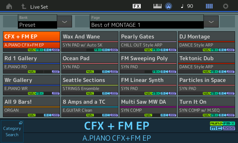
Notice the relationship between the 16 boxes in the screen and the right front panel lighted buttons… Shown below:
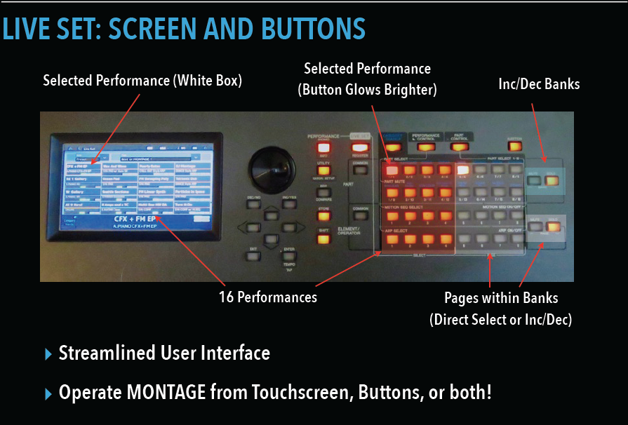
There are four rows of eight button, however, the left half, four row of four columns are illuminated buttons – dividing the entire grid of lighted buttons into two halves, left and right. One of the left half is glowing brightly – this represents the currently selected Performance in this Live Set. You can either touch the box in the screen or you can touch the dedicated button associated with that program. We’ll say this now and repeat often later, anything you can reach with the touch screen can be accessed via front panel buttons. It is your choice.
There is only one light illuminated on the right half of the 4×8 grid. The right side represents the Preset Live Sets. From the factory, 12 of the 16 Preset Live Sets are occupied. Use the upper set of two buttons marked “UP/DOWN Bank” to move between Preset, User, and later, your installed Library Bank Live Sets. Use the lower set of two button marked “UP/DOWN Page” to move between Live Sets within the current Bank. As mentioned there are 16 Preset Pages of Live sets, and there are 16 User Pages of Live Sets.
Navigating Live Sets: take a moment to read the QUICK GUIDE section on “Live Sets” in the Owner’s Manual starting on page 18 And 19.
Creating your own User Live Set will allow you to put together Performances you find immediately engaging. You can create sets containing your favorites. Don’t worry about overwriting anything, the Montage has plenty of storage. Read through “Creating Your Own Live Set” on page 30.
Category Search:
When you want to audition a specific Category of instrument, let’s learn to exit the Live Set grid and view the main Performance HOME screen. You have several ways to leave the Live Set and arrive at the main Performance screen:
Press the [PERFORMANCE (Home)] button, or
Press the [EXIT] button, or
Touch the “Home” icon in the extreme upper left corner of the screen
Any of these gestures will place you on the main Performance screen with the Performance name highlighted.
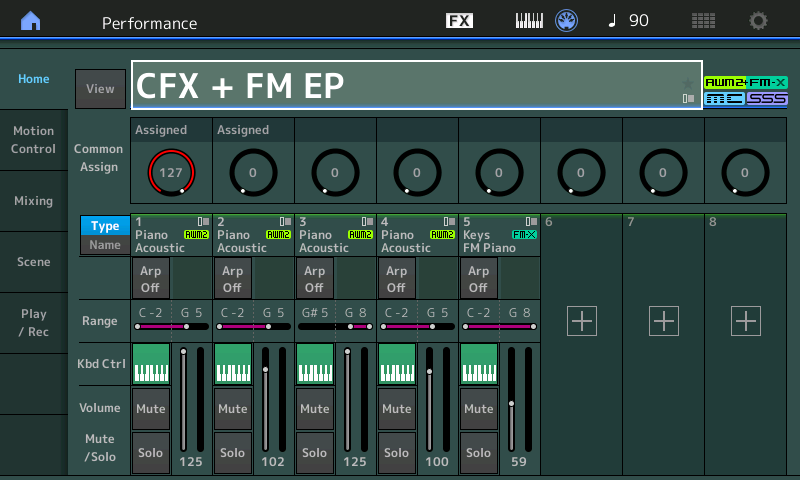
Performances are first divided into two main kinds… Single and Multi. This refers to the number of Parts under Keyboard Control (Kbd Ctrl) contained in the Performance which can be as few as one (Single) and as many as eight (Multi). In the screenshot above, “CFX + FM EP” you can see that this Performance uses five PARTS: Four to make up the CFX Acoustic Piano, and one to recreate the FM Electric Piano. The green (active) icon on the “Kbd Ctrl” row, indicates they will respond to the ‘local’ MONTAGE keyboard. The PERFORMANCE Name is highlighted – when this is the condition, pressing the [CATEGORY SEARCH] button will take you to the program listings:
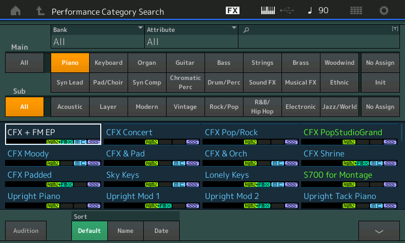
When searching for Performances you can view the listing in the “Default” order (as they are listed in the Data List Booklet), in alphabetical order by “Name”, or by when in time, “Date”, that you added it to your MONTAGE.
Those listed in green font are Single Part and those in blue font are Multi Part Performances. The significance of this we can deal with later, as it really only impacts things when combining (merging) Performances or working with recording the Montage. Listings of Performances in Category Search can be further defined by Preset (factory), User (your own custom/customized), from an installed Library or by the technology used (AWM2, FM-X, AWM2+FM-X). Along the top of the Performance Category Search screen you can see the defining search options for BANK and ATTRIBUTES.
Searching is very context sensitive… what this means is when you have selected a PERFORMANCE (highlighting the PERFORMANCE Name) and then hit [CATEGORY SEARCH] you will be searching for whole PERFORMANCEs (as opposed to single PARTs). When you tap the PART Name and select “Category Search” in the pop-in menu or you hold [SHIFT] + [CATEGORY SEARCH], the listings will be for individual selected Part. And when you have highlighted Arpeggios, or Waveforms and you hit [CATEGORY SEARCH], the search will be for Arpeggios or Waveforms, respectively. One of the first skills as a new user is to know what parameter is highlighted. Unsure about what that parameter is, this is where your ‘reference books’ come in very, very handy.
PERFORMANCE MERGE:
Take the time at this point to go through the QUICK GUIDE section of the Owner’s Manual (page 36) while seated in front of the instrument. It explains the basics of selecting a Single sound for a Part, adding a second sound layering them, then it covers adding (merging) a multi Part and creating a Note Limit region thus creating a split. These fundamental skills will serve you well – because it can get a whole lot more complex than this as you wade out into deeper waters.
Do’s and Don’ts:
Do: Remove and discard the protective plastic film that covers the screen when initially unboxing the instrument. It can interfere with your touch screen operation
Do: Explore categories of interest to you.
Do: Experiment with different approaches toward playing a sound, particularly if your first attempt yields less than satisfying results.
Do: Press the [AUDITION] button to gain a bit of perspective on what the programmer had in mind.
Do: Plug-in your (optional) Yamaha FC7 pedal into the Foot Controller 2 jack to control the Super Knob with your foot. For hands free Motion Control. This makes a huge difference!
Don’t: Approach every sound with a preconceived idea or lick you want to play. That is a different kind of search… When first encountering an instrument, be flexible, let the sound lead. Discover where it takes you. Later, when you are looking for a specific sound for a specific lick, you may want to adjust your search attributes to narrow the number of selections. The worst way to try out an instrument is to play the same thing on each and every sound. Your initial search should be ‘open’ and more general (like shopping for clothes or shoes), later you can get specific about what actually fits.
Remember: there are no good and bad sounds, one person’s opinion of a program can be vastly different from yours. Allow for this. Sounds are generally appropriate or inappropriate for a musical situation. A Honky-tonk piano sound is neither good or bad, by its overall nature, it is exactly right in certain situations, always remember that… Especially, if you’re one who always thinks there is one “BEST” piano sound.
Snorkeling, Scuba Diving and the Art of Sound Design:
A word on Multi Part Performances – these come in two general unofficial categories: those that are traditional Splits or Layered sounds and those that are like mini-compositions which you set in motion with a single note or a chord. Approaching the Split/Layer type is usually very intuitive because you are creating the music by playing the keyboard in a traditional fashion, but with these mini-compositions you are the trigger that puts all this bottled potential energy into Motion. For some people this is heaven – for others they have no idea how to interact with these inventions.
You can stay near the surface and enjoy MONTAGE from the snorkeler’s view, or you can dive deep and get out your scuba gear… when Nate Tschetter, Yamaha Marketing Manager first hipped the product specialist staff to what was on offer in MONTAGE he described it with this swimming analogy, and it is so apropo. We will have both types of articles here on YamahaSynth. So if you only want to wade out a little bit or you’re ready to dive for the Mariana Trench, we hope to have articles of interest for you. Let us know what you’d like us to cover.
Let’s use the appropriately named “DJ MONTAGE” as an example. You might feel that the composition is already done, and much like a DJ, you are simply putting the turntable in motion. What’s left for you to do? If you are asking that question… Move on and come back to this later. But be aware that what you are hearing is a programmer combining the Motion Control Synth Engine’s various tools (arps, motion sequences, automated controllers, etc.) into a musical montage. It’s sound designing. It’s very much like when working with a room full of analog modules and patch cables, where you are putting in motion a musical patchwork of connections. Here you can potentially have 64 Oscillators (or more), 64 Filters, 64 Ampitude Envelope Generators, tons of LFOs, Effects, even external sources all patched together to create a musical result.
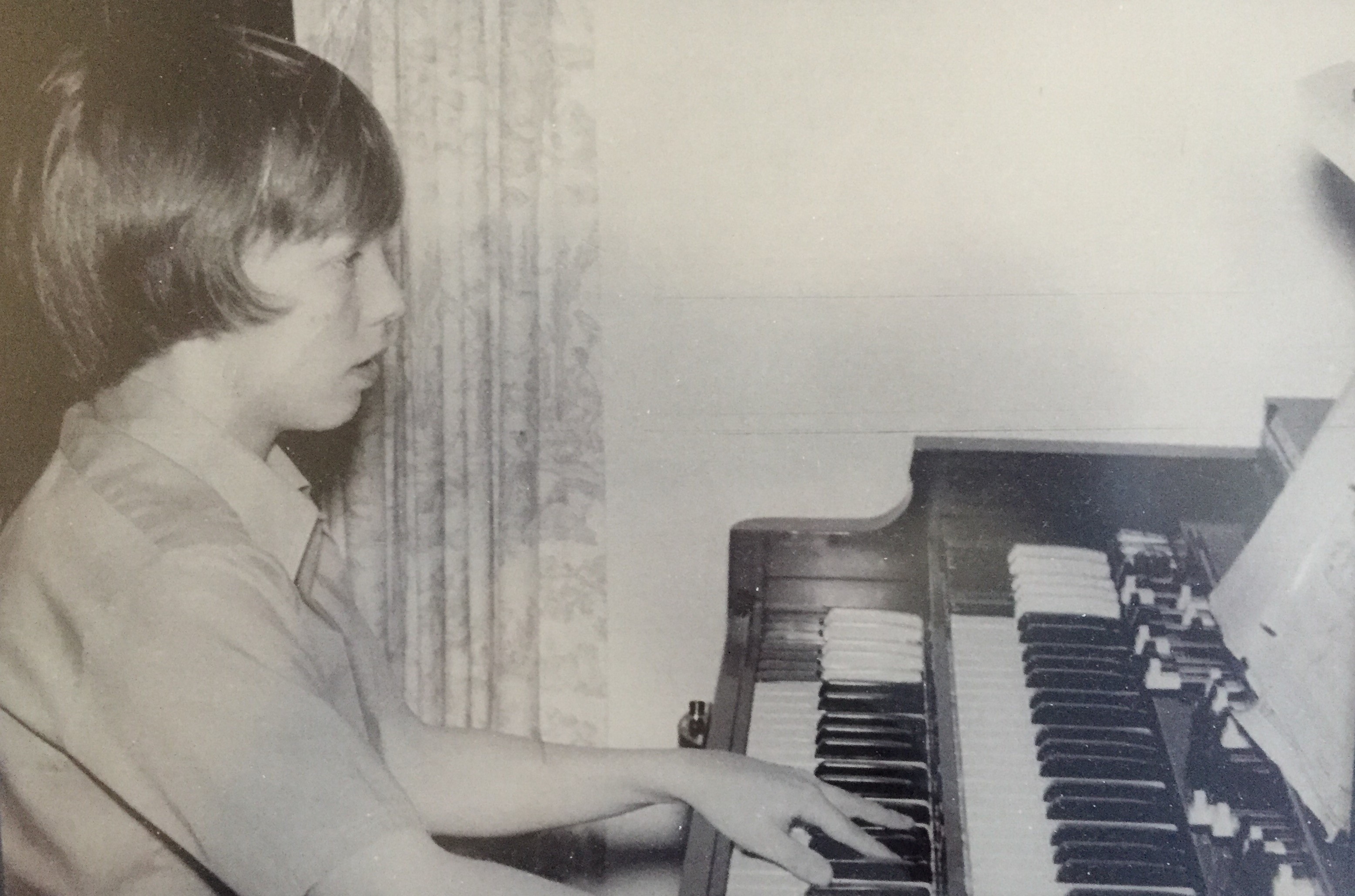
I learned synthesis on a room full of ARP 2500 modules back in the early 1970’s – where creating music was about patching Oscillator to Filter, Filter to Amplifier, and while the “preset” had not been invented at that point in synthesizer history (seriously, it was still years away), anyone sitting down to interact with a student’s patched creation would have an entirely unique experience based on how they chose to put the creation in motion. The patched creation was simply “potential energy” – the person interacting with it provided the “push” to turn it into “kinetic energy”. Sometimes that was by triggering a key or activating a switch. These MONTAGE Multi Part, multi-instrument creations are musical and rhythmic environments/atmospheres that represent the “patching” of the various components by one of the Yamaha voicing programmers. You can choose to interact with it, edit it, learn from it, change it, or even ignore it. You put all this potential energy into motion by triggering a key, turning a knob, or flipping a switch. Every time you interact with it you may have an entirely different experience.
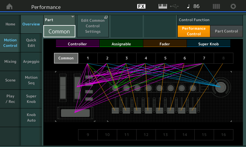
“Patching” in the MONTAGE is about assigning and mapping controllers to do your bidding…
But understand that your own personal creations can go in any musical direction you desire… In any kind of musical genre or one that doesn’t yet exist. There has never been a synth quite like Montage.
PERFORMANCES can be shaped into any kind of musical situation, any kind of musical genre. Imagine the very first synthesizers… Electronic music, back then carried a stigma. Not until early attempts at doing “classical” music did some folks start paying any attention. Soon synths were everywhere including in rock ‘n’ roll. The acoustic piano for many, many years was limited by similar thinking… It was only capable of chamber music, imagine that folks from 1700 hearing stride piano, or jazz, or rock n roll… Every time I hear someone say, “yeah, it’s only good for this one type of music” I have to remind myself, that not everyone hears the same or has the same vision when it comes to music and sound. Just because the organ started as an instrument exclusively for religious music doesn’t mean that’s all you can do with it. James Oscar Smith (better known to his friends as Jimmy) decided to change the role of the organ forever… building on the door kicked open by Fats Waller, Jimmy reinvented the role of the mighty B3 forever!
The MONTAGE is music in motion… Please bookmark the Official Yamaha Dowload site and check-in often for product firmware updates. As is Yamaha’s way, you can expect updated features, bug fixes, and improvements on an ongoing basis. Current firmware is 3.50.x
You can check your firmware version in [UTILITY] > Settings > System.
http://download.yamaha.com