Live Webcast from the “Winter Synth Jam”
Keyboard Magazine and Yamaha are hosting a live webcast from the Yamaha booth at Winter NAMM 2015. The webcast will feature:
- Artist interviews with Keyboard Magazine
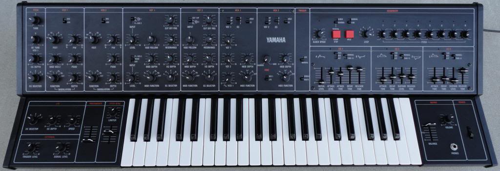
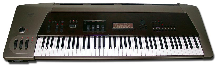
- A tour of our Vintage Synth display with yours truly!
- Stories behind the vintage synths
- A “Stump Bad Mister” Yamaha Synth trivia sweepstakes sponsored by Keyboard Magazine with great prizes: Keyboard Magazine subscriptions and Yamaha MX Synthesizers
- A live performance from EMKE
- Interactive chat during the webcast
The webcast will take place here on yamahasynth.com on Thursday, January 22 from 7:00 PM to 8:30 PM PST. Hope you can join us online! Click here to view the live webcast when it’s airing!