
Building a Custom Drum Kit
BUILDING A CUSTOM DRUM KIT
You can build your own custom Drum Kits. This is useful when you want to have a kick drum from one kit, a snare from another and toms and percussion from yet another. You can either build your own custom kits from scratch or you can simply edit any already made kit to suit your needs. We point that out because you may not want to spend the day picking 73 different sounds to create an entire kit. Remember, you most likely will not use all of the drums in a Kit – if you do, seek professional help! Your music may just be a bit too busy.
Go to [VOICE] mode and select a drum kit, you can press [EDIT] and start to customize the kit immediately. Like all EDIT functions in the XF you have two levels of editing: a general overall and a specific
• COMMON EDIT – overall parameters that are shared by the entire VOICE (Name, Kit Output Volume, Controller assignments, Arpeggio assignments, and Effect selection.
• KEY EDIT – (press Track Select [1] – shown below) individual keys contain a drum instrument, and here you will find all the parameters to control that individual drum instrument (Oscillator wave, assign mode, alternate group, effect routing, output routing, tuning, pitch sensitivity, filter, output level, amplitude envelope, EQ).
Each drum has its own EQ, amplitude envelope, filter, etc… so when we say each key is like a separate instrument we mean it has the same type of controls you would find on each normal Voice. That is why a drum Voice is so very big compared to a normal Voice. You have an unprecedented amount of control over setting up the kit. And like a drummer setting up the kit is important prior to playing. That said, during record (i.e., in SONG or PATTERN) you have real time control over Insertion Effect parameter via your physical Controllers.
Call up the drum kit you want to start with – it can be a PRESET or USER kit. (Preset Kits can be edited,. However, when you STORE your edit you will need to store it to a USER location).
• Press [JOB]
• Press [F1] INIT
Here you can select to initialize the entire kit “All Parameters”. This will change all 73 Keys C0-C6 to a default snare wave. You can opt to not initialize “all”, but initialize only a single Key, or just the Common parameters or both. And there is an option to: “Initialize the settings of the waveform assigned to the selected key”.
Initializing KEYS is the way to go, particularly if you simply want to combine some of your favorite principal drums into one custom kit. After you initialize the KEYS you want to work with you can go about selecting drum sounds for those keys. It is recommended that you do initialize a key prior to assigning a new ROM sample or a sample you have imported or created. The reason is: this way you do not inherit any parameters from the previous drum that occupied that key.
 From VOICE mode:
• Press [EDIT]
• Press Track Select [1] to view KEY parameters
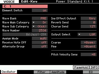
• Press [F1] OSCILLATOR
It is on this screen that you can select the Wave Bank, Wave Category, and Wave Number
On this screen, on the right column you can see the three EFFECT parameters: “Ins Effect Output”, “Reverb Send”, and “Chorus Send”.
An individual drum Key (Element) can be routed either to the INSERT EFFECT OUTPUT or to the System Effects (Reverb Send/Chorus Send). It is either/or. If you route a drum to the INSERT EFFECT OUTPUT, you will notice that the System Sends disappear. This is normal and denotes you have isolated this Drum from all “communal” (shared) System Effects.
If the INS EFFECT OUTPUT = ‘THRU’ then the drum is available to go through the Reverb and Chorus – you have Send amounts for each drum element. Only the individual Keys that have a Send amount to the Reverb and Chorus will be affected when the overall Drum Kit Send is increased or decreased. This means if you set the kick drum as “dry”(Reverb 0) but the snare drum “wet” (Reverb 25), turning up the Send amount for the entire Kit will only increase the a Reverb of the snare. The kick drum will remain “dry”.
You can setup a Compressor as one of the Dual Insertion Effects (this is a COMMON EDIT parameter) and then route individual drums either to the Compressor or not. In the two screenshots below, “C0” is not going to the compressor, while below “C1” is going to the compressor.
The Dual Insertion Effects in a DRUM VOICE can be “parallel”. What that means is: the two processors are separate. Or you can route INS A into INS B (or vice versa). In that scenario the output of one INSERT goes to the other. This routing applies to the entire KIT. (In the example used below, the routing is “parallel” – so each Drum can be sent to one or the other of the 2 Insert Effects…
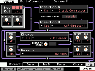
A good example of this (and a great one to learn about the routing within a drum Kit) is the Kit called “Garage Kit” PDR: 041(C09)
 It has:
INSERT A = Compressor: Classic Compressor
INSERT B = Distortion: AMP Simulator 1
— the insert effects are connected in “parallel”
Reverb = R3 Room
Chorus = VCM Flanger
From the main screen press the [F6] EFFECT button (this is a shortcut to the [COMMON EDIT] > EFFECT > CONNECT routing screen). Move your cursor to highlight the KEY parameter in the extreme upper left corner (if it is not already there).
You can HOLD down [SF6] KBD and touch a key on the keyboard between C0 and C6 to recall the routing of each drum Key. In the upper left corner you can see that each drum KEY will be routed to one or the other of the Dual Insertion Effect or it will be available for Reverb/Chorus.
While holding down [SF6] KBD you can quickly see and Edit if necessary – each Drum KEY’s routing through the effects. Notice that KEY “C0” is selected and that it is routed to the REVERB and CHORUS processors. It does not go through the Insertion Effects.
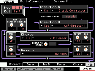 You can see that when KEY “C1” is been selected (kick drum), it is routed to INSERTION A, the Classic Compressor. In this Voice you can see that the Insertion A and Insertion B processors are routed in “parallel”. You could select to have the routing configured A>B or B>A or, as shown, parallel.
Because the KEY “C1” is routed to an Insertion Effect, the individual Reverb Send and Chorus Send are not active for this particular key. So if you want to send just the kick and snare to the compressor you can – when you [STORE] your Kit to a USER location, and then place it in a SONG MIXING or PATTERN MIXING program it will recall all of the edits you made here. There is a post-Insertion Effect SEND amount to the System Effects, and these will affect all drums returning from the Insert Effects.
Here is the same information as seen from the EDIT KEY screen for “C1”. Notice that the “Ins Effect Output” = ins A. There is no Reverb Send and no Chorus Send for this drum.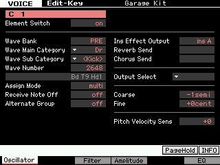
If a drum is routed to the System Effects (Reverb Send and Chorus Send) it will respond when you raise the overall REVERB or CHORUS send level in the MIXING program, if however, the drum KEY was routed to one of the Dual Insertion effects then it will not be effected by the increase or decrease in the SEND level – it will instead be routed to the INSERTION EFFECT as designated in your VOICE.
Also notice that if you choose to use internal INSERTION EFFECTS – the OUTPUT SELECT parameter is unavailable. When you want to route a drum KEY to an assignable output (FW), you would do so to process this drum externally. Therefore you would route it directly to the assignable output without using any of the internal effect processing at all. For details on routing of individual drum KEYS to FW Outputs please download and study the ADVANCED APPLICATION: FW AUDIO SETUP tutorial.
Edits to a Kit must be stored to a USER DRUM Bank location. You may wonder how the individual Key routing can take place when using this Drum Kit in a 16-Part MIXING setup (SONG/PATTERN mode).
If you route a Drum to an “assignable” or “FW” output, then in the SONG/PATTERN MIXING setup you will want to set the OUTPUT SELECT parameter = “drum” (shown below). The screen shot is from a Drum Kit selected as PART 1 of a PATTERN MIXING setup. 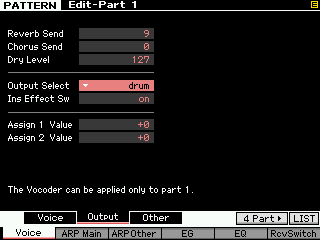 This setting for OUTPUT SELECT will recall all of your Output routings from the Voice mode. So it is totally possible to route individual drums to individual FW outputs when recording to your DAW software. This is extremely powerful and useful. It means that even though your Drums occupy a single PART of your 16 PART mix, and even though all their data is recorded on a single track, each drum can still be routed to an individual output. The Yamaha Steinberg FW driver allows you to have 16 audio buses out from the XF at any one time and any instrument (including individual drums) can be routed to a separate audio output. Other synthesizers might have to use a separate track to accomplish this type of advanced routing.
In order for the drum keys that are routed to the INSERTION EFFECT to access their Insertion Effect, the drum PART must be one of the eight PARTS designated to recall its Insertion Effects in the MIXING setup. Remember any eight internal PARTS can recall their Dual Insertion Effects when in a MIXING setup. The AD INPUT PART could be one of the eight PARTS.
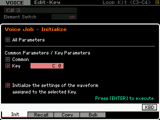 INITIALIZE [JOB]:
When constructing your own Drum Kit you will need to master the skill of initializing a KEY, rather than starting from scratch, you can edit an exisiting kit, customizing just the KEYS that you need. Here is how to initialize a single KEY:
Press [JOB]
Press [F1] INIT
Clear the ALL box, and set the attributes you need.
The other important skill is to COPY Drums from one place to another. In other words, you will find a Drum Kit in the Motif XF that is “All Kicks” – obviously a storage Voice, you can copy any drum from any Kit to another using the [JOB] > [F3] COPY
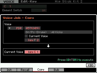
Press [ENTER] to execute.
When you complete customizing your own Drum Kit, press [STORE]. There are 32 User Drum Kit locations on board the XF. Additional Kits can be stored per Project in Cubase. And additional Kits stored as VST PRESETS in the convenient MediaBay Sound Browser.
