Is there a way to sync the LFO of a Part to an external clock? It seems to only run freely.
[quotePost id=118623]Is there a way to sync the LFO of a Part to an external clock? It seems to only run freely. [/quotePost]A “Part LFO” can be sync’d to MODX/MODX+ Tempo using “Tempo Sync” = On. If the MODX’s global Tempo is then sync’d to external clock, the Part LFO will follow suit.
Tap the Tempo Setting at the very top of the screen to take the shortcut to where you can set “Sync” = MIDI green is active.
There are individual Element LFOs… You do not specify which LFO you are attempting to use. Here’s how the Part LFO works: taken from the LEARN area on this site…..
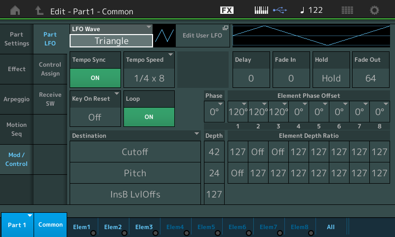
In the screenshot below from Single Part Performance - "Da Thumperz": we are looking at a Single Part with 3 AWM2 Elements active (fyi)

PART LFO and the Destination Box: The PART LFO, in this case, is controlling the movement of the Filter Cutoff Frequency, Pitch variation and applying a level offset to Insertion Effect B Level Offset parameters (Dynamic Phaser). The PART LFO allows you to apply a Low Frequency Oscillator to three Destinations and to scale the Depth on a per Element basis where appropriate. The routing options for control are any assignable parameter within the PART's current Insertion Effects, in addition to Level, Pitch, Cutoff, Resonance, Pan or Element LFO Speed. The PART LFO can be sync'd to the TEMPO and can be set to musical values from a 16th note out to 16 quarter notes. It can be set as a one shot (acts like an envelope) or it can be set to loop. The Phase can be offset per Element which adds dimension to the movement.
“1/4 x 8” is equal to eight quarter notes. It is written like this (musical subdivisions) to avoid having to deal with time signature. In 4/4 time eight quarter notes span 2 measures. You will find values as small as a 1/16 and dotted values through 16 quarter notes.
Learning to work the Destination Control Box is worth some time and experimenting. In this particular PART, the three selected DESTINATIONs (shown above) are "Cutoff", "Pitch" and "InsB LvlOffs" (a parameter within Insertion Effect B).
In the screenshot the Triangle Wave’s phase is set to 0 degrees. You can offset the start - set to 90 degrees to have it start at maximum (see the graphic change to indicate the change). Set it to 180 degrees to have it initially descend rather than rise.
Each AWM2 Element can be individually offset, as well, when the selected Destination allows.
