Hi All,
I have created a performance where if I turn on Assign Switch 1 I get the sound I am after. Not sure technically what it's doing to the bass sound, but it works for me.
I would like to set the performance such that the Assign Switch is turned on automatically with the performance and/or scene.
How do I do this, and where do I see what the assign switch is doing?
I think it's under the Mod Control / Control Assign area?
Hi Dave, Thanks for the question...
The Assign Switches 1/2 will normally default to Off.
This is normal — all physical controllers will naturally RESET to a default condition without you having to do anything other than recalling the program. Example, the MW will RESET to sending a minimum value (0) regardless of where you physically last left it. A Foot Controller, by contrast, always defaults to maximum (127).
Back before MIDI — If you left your MW up the next sound you recalled would begin with the MW assigned parameter being applied. PB Wheels (before the days of spring loading them so they automatically returned to 0 pitch change) also where live at all times. Some controllers RESET to a center value — those can move above and below this default (or left and right of the default).
MIDI’s ability record controllers required that a RESET condition be established for each to return to upon command. The command is a RESET ALL CONTROLLERS message. In general, they return the synth to a default condition where it can sound normally.
The Assign Switches 1/2 will normally default to Off.
There are a couple of ways around this:
1) Find the parameter that it is controlling... then set that parameter to the exact condition in which you want the sound to be when it is recalled... then you can reverse the application of the Assign Switch such that the AsSw *defeats* the application, rather than turning it on, it defeats the application.
2) You can Set the “Controller Reset“ function so that your Controllers are live (careful what you wish for) they do not RESET automatically. Controller Reset = Hold. (Found on the MIDI I/O screen.
We recommend option 1... it is more surgical (means you can target just what you need without inheriting a bunch of consequences you can’t possibly be ready for by defeating the entire Controller Reset function).
Extra Credit:
How to find out what it is doing
From the HOME screen
Press [SHIFT] + [HOME] to go to the “Motion Control“ > “Overview” screen
Here you can see the various front panel assignable controls.
You can see the number of Parts in this Performance — the AsSw will be controlling Parts separately.
Initially “COMMON” is selected for the PART
Press [AssignSw1] if it is controlling a Part you will see a line *highlighted* between the Switch and the Part numbers it is interacting with.
Set the PART number as indicated where it has an assignment.
By setting it to “Part 1” you’ll see a shortcut box “Edit Part 1 Control Settings” appear
Tap that box.
Press [AssignSw1] to recall all parameters assigned to this Switch as “Source”
The “Destination” is the controlled parameter.
Often it is an abbreviation. If you don’t know what it means you can look it up in the “Synthesizer Parameter Manual” pdf manual or you can ask here. Now you can locate the Parameter... navigate to that area of the Part architecture and edit the value directly.
Set the value of the parameter to meet your requirement — then you can use the Assign Switch to flip it to minimum value (whatever you determine that is) by setting the “Ratio” to a negative value. This works because the Assign Switch defaults to 0 minimum. So by setting minimum to the actual value you want, and then reversing the direction of application, you can now have the switch work to disengage/engage but start as you desire.
The Control Assign screen shows you how the parameter is to change when the Switch is activated. The graphic shows on the left side the condition of the parameter initially... you can either increase it or decrease it from the initial setting. A ramp going uphill is a switch that moves from current to more by activating. A ramp going downhill is a switch that moves from current to less by activating.
Let us know.
Thanks BM
Working through it - initially I took the ratio as being the actual figure to increase or decrease the parameter, but it seems to be that it is truly a ratio, and therefore while the ratio might be set at a certain figure, the parameter value may have to be set to a different figure to achieve the ratio change.
Also I am finding on another performance that the AssnSw1 definitely affects a part. however when I go through all the steps you mention and on the final step I set the "Display Filter" to "AsnSw1" there does not appear to be any parameter or destination set ?
To second Dave's question: take, for example, the stock performance "Jazz To All Out 2". Its "ASSIGN 2" definitely does something (gives a bit of a volume bump, and, I think, a bit more "grit" -- so I'm guessing it turns a "gain" or "drive" knob somewhere).
If you follow it from the "Motion Control" > "Overview", it says it controls "Part 2" (and only that), but its "Control Assign" page is blank.
Working through it - initially I took the ratio as being the actual figure to increase or decrease the parameter, but it seems to be that it is truly a ratio, and therefore while the ratio might be set at a certain figure, the parameter value may have to be set to a different figure to achieve the ratio change.
That is exactly it. The Ratio is truly a ratio! The target parameter (called the “Destination”) is what is being changed.
If you follow it from the "Motion Control" > "Overview", it says it controls "Part 2" (and only that), but its "Control Assign" page is blank.
If the Control Assign is blank, then it is possible the Overview is indicating that the AsSw is being used to perform XA CONTROL (Expanded Articulation Control) which determines how individual Elements will behave within the Part.
The Assign Switches have two roles — assignable via the PART Control Assign setup as a switch and as articulation control for AWM2 Elements (Oscillators) See example below.
To second Dave's question: take, for example, the stock performance "Jazz To All Out 2". Its "ASSIGN 2" definitely does something (gives a bit of a volume bump, and, I think, a bit more "grit" -- so I'm guessing it turns a "gain" or "drive" knob somewhere).
If you follow it from the "Motion Control" > "Overview", it says it controls "Part 2" (and only that), but its "Control Assign" page is blank.
This is a Tone Wheel organ sound. Here is how to go about exploring…
Recall the Performance ”Jazz To All Out 2”
Press [SHIFT] + [HOME] to see the “Motion Control” > “Overview” screen
Initially, the screen shows “COMMON”
If you press [A.SW 1] you will see it indicate that it is influencing both Part 1 and Part 2
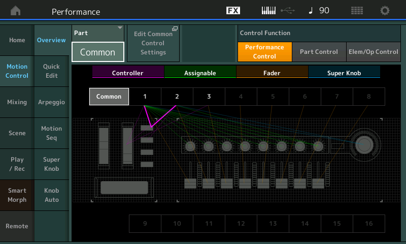
If you press [A.SW 2] you will see it indicate that it is influencing only Part 2.
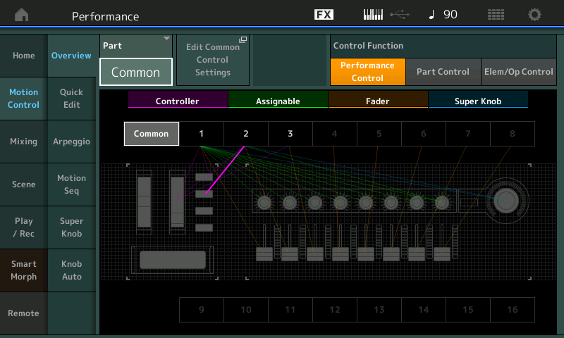
Let's Explore Part 1 first
Change the “Part” from “Common” to “Part 1”
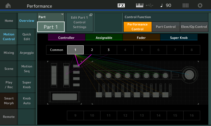
Tap the box “Edit Part 1 Control Settings”
You will be taken to the “Mod/Control” > “Control Assign” screen for Part 1
Make sure the “Auto Select” option is active (green)
This allows you to recall the assignment by touching the Controller.
You will discover that the [A.SW 1] is influencing three parameter Destinations: #5, #6 and #15
Element LFO Pitch Modulation Depth, Element LFO Amplitude Modulation Depth, and (Part) Volume
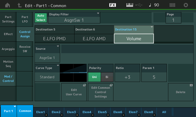
Along the bottom of the screen you can see Part 1 is 8 Elements (bright blue indicates active Element)
_ If you move the cursor to highlight “Destination 5” - (E.LFO PMD) you learn that all 8 Elements are set to change when the Switch is active. PMD in musical terms is “vibrato”.
_ If you move the cursor to highlight “Destination 6” - (E.LFO AMD) you learn that all 8 Elements are set to change when the Switch is active. AMD in musical terms is “tremolo”.
_ If you move the cursor to highlight “Destination 15” - (Volume) this is Part Volume (and is not selectable per Element). The Ratio settings of +3 (for the Volume) means pressing the [A.SW 1] will increase the current Part Volume.
Say you raise this to a higher positive number … you should hear a significant increase when the button is engaged… lower it to a negative number… you should hear the Part Volume reduced. The current stored Part Volume is 100, so you are offsetting from that stored Part Volume.
Let’s explore [A.SW 1] and Part 2
[A.SW 1] is also set to influence Part 2. Change your view to Part2 (you can do so in the lower left corner tap the blue box “Part 1” to see the pop-up menu, select Part 2.
Here you will see this is a 2 Element Part (along the bottom of the screen Elem1 and Elem2 are bright blue).
The [A.SW 1] is set to change the same targets for this Part - “E.LFO PMD” Destination 6, “E.LFO AMD” Destination 7, and (Part) “Volume” Destination 8
However, if you look at the Element Switches for the LFOs — Elem 1 = On, and Elements 2 = Off — only Element 1 of the two Elements is set to respond to PMD and AMD. Naturally, in Destination 8 (Part) “Volume” you don’t get individual selections - it affects the entire Part Volume (All Elements together)
Let's Explore [A.SW 2] on Part 2
Press [A.SW 2] it is influencing Part 2
However when you press [A.SW 2] and look for a Control Assign setup — there is no assigned Destination. This will be your clue that this Switch is set to do XA CONTROL - Expanded Articulation Control…
To view this assignment, simply tap the word “All” along the bottom of the screen. Here you will be able to view all Oscillators (Elements) and what they are set to do.
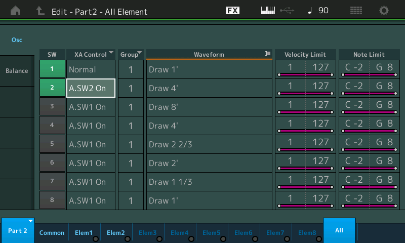
You will notice that Element 2 (which when you isolate it, you’ll discover) is playing the role of percussion. When [A.SW 2] is activated you will be adding the “Draw 4’” Element.
Having trouble hearing the difference? — use your Mute and Solo buttons to isolate just the components you wish to hear.
... adding:
When looking at the curves (a standard curve is a ramp that, when positive ratio, ramps up as you go right) - it's helpful to know how this image of the curve relates to the source and destination. The source is a controller and the controller in this case is an assignable switch. The destination is a parameter and the parameter in this case is "Mono/Poly".
The graphic of the curve has an X and Y axis. Going left and right is the X axis. The Y axis (up and down) is the height of the curve at any given point. If we are at the far left of the graph, then Y=0 and this means when the source controller is outputting 0. If we are at the far right of the graph, then Y=127 and this means the source controller is outputting 127.
Some source controllers can output the full range. From 0 to 127 and all values between. The modwheel is one example of this type. When it is fully "down" until it stops it outputs 0 and when it is rolled all the way up until it stops it outputs 127. When rolled in the middle the value is 64 and the modwheel can reach all points between.
The assignable switches only assume two values. When OFF - the assignable switch outputs 0. When ON - the assignable switch outputs 127. Therefore, the curve only uses the "Y" values (parameter offsets) either at the far-left of the graph when the button is off or at the far-right of the graph when the button is on.
In my opinion, it would be helpful to have the formula for the standard curves based on ratio so one could know for the ramp how to resolve the Y parameter offset value at any controller input value (X) at any ratio. This way one would know, on paper, why the value of 17 for the ratio is needed. HOWEVER, it's not absolutely necessary because one can experimentally determine this. You would set the default value appropriately, turn on the assignable switch which is your source controller, then increase/decrease the ratio until you find where the impact of the curve changes the function. It's easy to hear the difference between mono and poly. Indeed when you cross from a ratio of 16 to 17 - you hear the offset is large enough to change from poly to mono (or vice versa depending on where your programmed value starts you from).
Current Yamaha Synthesizers: Montage Classic 7, Motif XF6, S90XS, MO6, EX5R
