Notifications
Clear all
Topic starter
I got this diagram from a SY-99 manual I found on line. Is there a similar diagram available anywhere for the
Motif XF?
Or does this diagram accurately represent AWM2 on the Motif XF.
I ask because I'm trying to get an accurate logical picture of the signal flow or audio path on the Motif XF. I have Motif OM, RM , DL, and Synthesizer Parameter Documents. But all of these really give a 50,000 ft logical view that doesn't quite answer my questions.
For example I would think that from a logical point of view the insert effects fit before the amp envelope generator. In particular, I'm messing around with the ring modulator, the dynamic filter and the other modulation effects that are categorized as TECH effects. I'm having big fun in some voice design right now on my Motif XF. From a logical perspective I would think that these insert effects are applied before the AMP Env Generator.
Most of the logical diagrams in the docs put the insert effect block after amp EG. I understand why for some purposes the diagram might be drawn as such. But it doesn't seem to jibe with what's actually happening.
Sound source is Filtered, then modulated (in some form) and then sent to the Amp. The insert effects (Tech effects in my case) are modulators right? They are not modulating the sound after output is over but in between note on and note -off Attack thru Release.
To all, I apologize for the dense question here, but I'm looking for a somewhat complete logical view of the audio path or signal path of the AWM2 engine up to the point of the System Effects. At this point I am not really interested in where the System Effects, Or Master Effects fit in the logical view. I am interested in where the Ring Modulators, Dynamic filters, AM Modulation and LFOs that are found in the TECH effects fit in the logical picture of an AWM2 Element on the Motif XF.
Also, in pouring over the all the documentation I could find on AWM2 engines in the synthesizers leading up to Motif, I noticed that the farther in time I went back, the more complete, or detailed the Synth Audio Path/Signal Path diagrams seemed to be. I imagine they've been simplified because the average musician probably is not interested in this level of detail, or maybe this level of detail just added to tech support calls/headaches. But for some of us the more detail the better. Especially in this day and age where there is a growing interest in synth engines, signal paths, and audio paths. Hopefully Yamaha has a nice complete relatively detailed audio path diagram somewhere/??
Posted : 22/09/2019 11:53 pm

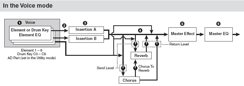
This is the general Signal Flow for a Motif XF Voice.
The Element, which includes the Oscillator (PEG), the Filter (FEG), the Amp (AEG), is the instrument. Let’s use an electric guitar as our real world example.
The guitarist plucks a quick muted note, that whole description takes place on the instrument... if the guitar output is Inserted into a Distortion box and a Wah Pedal as it’s two Insertion Effects, they receive the envelope created by the quick muted pluck. They (the Insert Effects) do not create the envelope. The receive the signal after the envelope has taken shape.
Insert Effects that do seem to influence or change the envelope must have some kind of “Feedback” parameter, that capture the short muted pluck and turn it into something else by cycling it around and around....
Please the following article for more details:
Motif XF Introducing the Motif XF Effects
Posted : 23/09/2019 12:42 am
First, thanks BM., for responding to my post. I know that if anyone can give me a correct answer to my question you can.
Hopefully, I'll be able to clarify my question. Please bare with me. I may not be asking the question correctly. I am very familiar with the diagram you posted. Notice that the diagram you posted does not show the PEG, FEG, or AEG. I do understand they are in the instrument. And I do understand that in the real world insert effects are outside of the instrument. And the signal leaves the instrument goes into the insert effects and then to the amp or board or DI or whatever. But in this case we are talking about DSP. And we are talking about the logical path of the signal. Right?
Doesn't the AMP envelop deal with the loudness of the sound over time. From the time a note is pressed until it is released, the level of the sound is governed by the AMP EG. That is If we are talking about the same thing.
So anything that we actually hear is happening during the the Init, Attack, DCY1, DCY2, REL, SUS cycles of the AEG. Right? If I set the level of the AEG to all to zero for all elements, No effects will be heard. Nothing will be heard. Right? In your guitar example, in the real world that guitar is making a sound, even if the AMP is turned to zero. In DSP land I'm trying to picture if the Waveform->Filter->Modulator->AMP is the flow. And the insert effects are in the Modulator category.
So what I'm trying to get at is as far as the audio path is concerned "logically the insert effects are in play before the signal gets to the AEG. That is, whatever sound I have, and whatever modulation I'm doing is going to be heard during the time frame AEG is active not afterwards. Is this correct?
It seems the insert effects must logically precede the AMP block or am I getting it wrong? I've attached a logical block diagram showing what I think is going on.
Also, Is the SY-99 diagram that I posted representative of current AWM2 element logical architecture? I've looked at this same Diagram for the EX5, and SY-77 and they seem to support my assumptions. Should I post these diagrams to clarify my question?
I don't want to press your patience, I'm just trying to get the correct picture in my head. This Diagram represents what I'm grasping at.
In the diagram that you posted., is the AEG active From Step1 to Step6?
Posted : 23/09/2019 1:57 am
Each Element is a complete synth. The “What is an AWM Element” diagram is spot on through to today except for the inclusion of the connection to an “AFM” Operator. There are no Insert or System Effects in that diagram... because they come after all of this...
It shows four main blocks (left to right)
The Waveform block (Oscillator) —> Filter block —> Amplifier block —> Pan block —>
Then the signal goes to the dual Insert Effect block. The dual Insert Effect block has 8 inputs. Each of the 8 Elements is routed to either Insert A or Insert B or bypasses the block altogether.
The Insert Effects get patched into the signal flow after the Element Pan block. Each Element goes to either Insert A, Insert B, or Thru.
In the first block “Waveform block” you’ll find the PEG, you’ll find an input for Element LFO, input for Velocity Sensitivity etc
In the second block “Filter block” you’ll find the FEG, you’ll find an input for Element LFO, input for Velocity Sensitivity, etc.,
In the third block “Amplitude block” you’ll find the AEG, you’ll find an input for Element LFO, input for Velocity Sensitivity, etc.,
In the fourth block “Pan block” you’ll find a Pan EG
When you set Element Pan to “random” for example, going into a stereo Insertion Effect, the Pan information is respected.
Posted : 23/09/2019 3:06 am
BM Thank you for verifying the "What is an Element" diagram relative to the current AWM2 engine in the Motif. So that answers part of my question. Again your patience is very much appreciated.:)
Okay here are two questions that may clarify my remaining question a little more.
1) Do the insertion effects modulate the sound at the oscillator/element level prior to the elements being summed?
2) Is the Amp Envelope still active while the insertion, system and master effects are being heard?
Here are my assumptions:
The Pitch, Filter and Amp envelopes run concurrently (or in parallel). They each happen between Note on and Note off. Right?
We also hear whatever insert, system or master effects that are being applied between Note On and Note Off
So the effects would have to be applied to the signal in parallel with the envelope execution correct?
Basic Subtractive Synth Structure (applies generally to any subtractive synth) :
Source -> Filter -> Modulators -> Amp
The envelopes, and the insertion effects directly modulate the oscillators(i.e. elements) at the element level right?
Because the Insertion Effects can be applied on an Element by Element basis, It appears that the Insertion Effects modulate the signal prior to the elements being summed together to create the voice.
There is a difference in modulating the elements after they've been summed (e.g. at the voice level), and modulating the elements before they've been summed(i.e. at the oscillator level).
If the insertion effects are modulating the signal at the element level, that modulation seems to be occurring at the very least in parallel with the amp envelop, which means that the insertion effects can't be applied after the amp block Unless there are multiple output or amp blocks. Are there? None of the diagrams show multiple AMP or Output stages.
It almost seems like we are equivocating the common steps in voice design with signal(audio) path.
Under TECH effects(insertion effects) for the Motif we have Ring Modulators, Dynamic Filter, AM Modulator, and a Filter Modulator. Through the insert effects these can be applied at the element level. And they appear to be modulating the element prior to element summing. This suggests that they are not applied after the AMP block:o
Perhaps this may shed a little more light on my question.
The diagram you originally posted shows the General Signal Path Of a Motif Voice.
I am interested in the General Signal Path Of a Motif Element (prior to summing with other elements).
The answers to these questions are helping me with some of the voice design that I'm doing on my Motif XF. If I can get this signal flow right it could shave many hours (possibly days) off of what will already be way too much trial and error.
Does Yamaha have a more detailed diagram of the current AWM2 signal path that can be shared with non Yamaha employees or the public?
Thanx again for your patience and responses in advance.
Posted : 23/09/2019 4:52 am
