

Tagged Under
Mastering MODX: An FM-X Exploration, Part III
This article references content saved in MODX Connect, the VST/AU and standalone software component for capturing and recalling MODX Performances:
- Get MODX Connect for Mac or PC here.
- Get the file associated with this article (P1.X8B and P2.X8B in a single .zip file) here.
- Get P1-P2.X8B and P3-P4.X8B in a single .zip file) here.
In this chapter, we’ll take a look at two more Single PART Performances, each one made from just a simple two Operator stack. These are exactly like the previous examples, with the exception that the Modulator to Carrier tuning Ratio is 1:1 here. It was 2:1 in the previous examples – and this will give us yet another array of timbres we can build – as your ears will tell you. We will apply the same 8 Assign Knob parameters as in the previous examples and, again, show that with just these parameters, we can fashion a very wide variety of initial FM-X waves.
The zipped download (at the very bottom of this article) has two (P1.X8B and P2.X8B) MODX Connect Performances. Unzip them and use MODX CONNECT to BULK them into the MODX – You can bulk the first one, press [STORE] to write it to a USER Bank Location, then bulk the second one over.
COARSE and FINE TUNING – The Ratio Setting
We’ve mentioned that these two new FM-X Performances are built from a Modulator to Carrier tuning Ratio of 1:1, while the two previous examples were built from a tuning Ratio of 2:1. In an attempt to avoid too much mathematics, we dove right into editing existing structures. But let’s back track a bit and talk a bit about this fundamental FM concept.
Your typical FM tutorial will always begin with the fundamental mathematics of these Sine Wave Ratio relationships. Since we bypassed this and went directly to listening experiments, we want to be sure you understand it. And that you also don’t bog yourself down with starting always with a SINE Wave. The basic Tuning of the Operators greatly affects the tone you get when they interact:
- In short, a 1:1 relationship in the Tuning of the Modulator to the Carrier will produce all harmonics in the series.
- And a 2:1 or higher relationship in the Tuning will produce just the odd numbered harmonics in the series.
Yeah, but what does that really mean? When seeking to understand the Tuning of an Operator, we must look at the Coarse and Fine tune settings which are referred to as Ratio.
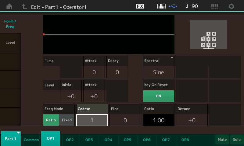
Let’s take a look: The Coarse setting is ‘1’, the Fine setting is ‘0’: translates to a RATIO setting written 1.00:
- Press [EDIT].
- Press [PART SELECT 1].
- Touch “OP1” along the bottom of the screen (or Press the first button in row three on the right front panel which is Operator Select [1]).
- Touch “Form/Freq” in the first column.
Operator 1 as Modulator:
Operator 2 as Carrier:
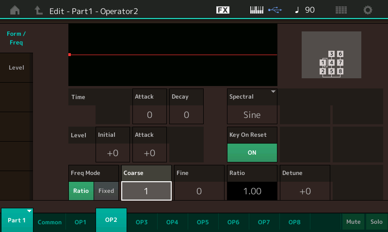
This is how MODX represents “1.00” as the Ratio. What this means is when you play the “A” above middle C, it should naturally reproduce the pitch A-440. If the Ratio is 1.00 that is exactly what you will hear because A-440 x 1.00 = A-440. If the Ratio is 2.00 (Coarse = 2) what you hear will be A-440 x 2.00 = A-880.
When both the Modulator and the Carrier are the same value – the resulting harmonics generated will be whole integer multiples of the fundamental pitch. All harmonics are reproduced.
When the Modulator is 2.00 and the Carrier is 1.00 – the resulting harmonics generated will be every other harmonic (only the Odd harmonics) sound familiar?
Every whole integer multiple (every harmonic in the series) results in sawtooth waveforms. Every other harmonic in the series results in a pulse wave. When the relationship is exactly 2 to 1, the result is a special equilateral Pulse waveform called the “Square”. As the relationship gets higher and higher 3 to 1, 4 to 1, 5 to 1 the result are Pulse waves but the sound gets narrower and narrower, more nasal sounding, pinched.
Experiment with COARSE Tuning. Set OP1 Coarse = 2, OP2 = Coarse = 1, hear the square wave tone. Increase the OP1 Coarse to 3, hear how the sound gets narrower.
If you change the Modulator’s FINE tune setting, you will start to hear what we describe as bells – when the mathematics is not whole numbers, we describe the tone as a bell tone. You will hear why immediately. Because the Tuning of OP1 and OP2 are different than in our previous two examples (P4 and P3), even if you make the same 8 Assign Knob Settings you did previously, the result will be dramatically different.
The important thing to realize is that starting with the basic mathematical relationship between the Modulator and the Carrier has an influence on the tones/timbres you will be able to construct. You will hear immediately, that the sounds we are able to get from this pairing of Modulator: Carrier, differ in character from those we heard in our examples, P4 and P3. That is what is important here. If the math makes no sense, don’t worry about it. But don’t be afraid of it either, it is musical mathematics and useful (at times). Now on with our experiments!
Performance P2
Examine and compare the settings for Performance P2 and P1 from the perspective of the 8 (PART 1) Assign Knob parameters:
From the HOME screen, select PART 1:
P2 – Assign Knobs:
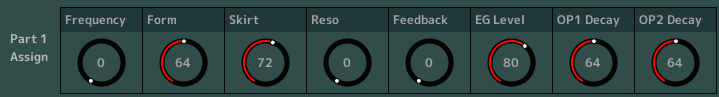
P2: Spectral “Form” (64) is in the “ODD 1” family (pulse wave) range, with the Skirt set a bit more than half-way, to taste – move Part Assign Knob 3, “Skirt”, to hear the subtle tone color change from smoother (lower) to more edgy (higher). Play in different ranges on the keyboard to check out how the timbre changes as the Skirt is unfurled. As you continually tap the keys, change the setting and hear how the timbre changes. Then stop and play it at a setting to get a feel for how it plays.
Explore the settings here as you have learned to do in the previous two articles. The arrangement of Modulator (OP1) to Carrier (OP2) is the same in all examples – what is changing is how these eight Assignable Knobs are set to alter the resulting timbre.
Quick Reminder: the “Frequency” Knob is changing the tuning of the Modulator (OP1); “Form” is a pulse wave (Odd 1); “Skirt” will allow more harmonics on all Forms except the Sine; “Reso” will work only when Form is above 98 (Res1/Res2); “Feedback” will intensify the energy of the Modulator; “EG Level” is offsetting the envelope of the Modulator; “OP1 Decay” shortens/lengthens the Modulator; “OP2 Decay” shortens/lengthens the Carrier.
FORM Values:
P1 – Assign Knobs:
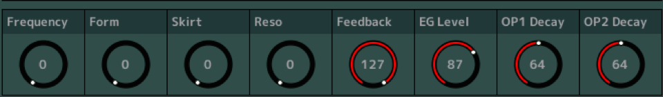
P1: Spectral “Form” (0) is the traditional “Sine”, “Feedback” is at maximum – move AsgnKnob 5 to hear the affect of the Modulator set to Feedback on itself. From round (0) to nasal (127). There are times when the Feedback parameter had a subtle effect on the overall timbre, but here, with “EG Level” up a bit – raise it to 114, then changing the amount of Feedback routed through the Modulator has a profound affect. You can begin to hear the creation of “noise”.
Noise by definition is the opposite of Music (no jokes, please, about some music being noise), but Noise is the result of all frequencies combined simultaneously, in differing balances. While Music is the antithesis, it is the organized vibrations that relate to each other in a supportive way. While Noise is chaos, Music is order. Noise as a waveform looks very random, Musical tones have a pattern that repeats.
Take the “EG Level” up to 127, and as you increase “Feedback” you will hear a bit of noise, sounds like the whoosh of wind or the ocean surf.
Return your settings to the P1 “starting position”. Explore the setting here as we have learned in the previous examples. With Feedback on the Modulator, you will notice a radical “ringing” when the FREQUENCY (Knob 1) is swept. Because we are tuning the Frequency of the Modulator and there are non-whole integer relationships being swept – you will hear what we describe as bell tones, ring modulation, ringing… (A little math here: When the Modulator to Carrier RATIO is whole numbers like 1:1 and 2:1 or even 4:1 or 4:3, the results are musical tones that we describe as pure, but when fractions are involved like, 1.50:1 or 3.50:1 or 1.73:1 we describe the tone as ‘ringing’ or a bell tone).
In this particular PART, “P1”, a Compressor and an Auto Wah TYPE are assigned as Insertion Effects A and B, respectively. When working with FM-X you can send the CARRIER’s output into the Insertion Effects. To view this routing:
- Press [EDIT].
- Select PART 1 to view PART 1 parameters.
- “Part 1 – Common” appears in the lower left corner.
- Touch “Effect” > “Routing”:
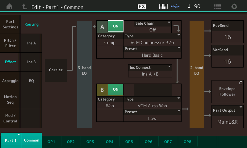
Here you can see the signal flow going left to right across this screen: the Carrier is being routed through the 3-Band EQ, which is routed to INSERT A (“VCM Compressor 376”) which is routed to INSERT B (“VCM Auto Wah”), which is routed to the 2-Band EQ, which is then delivered to SYSTEM processing – Reverb, Variation, a send is available to the Envelope Follower, and the PART Output assignment.
The Auto Wah Effect seems to make this nasal Clavinet-type tone complete somehow. The Wah Effect, in itself, is a moving filter. The Modulator “Feedback” (Assign Knob 5) seems to revel in the Auto Wah.
Task
Try to make as many different tones as you can from manipulating just the 8 Knobbed parameters presented here in this example. Make yourself comfortable with both when and how these parameters will interact. Know that when they have, or seem to have, no effect on the result, it is probably because the context is not proper. You should not expect to hear RESONANCE, for example, when the Spectral FORM is not “RES 1” or “RES 2” (in the range of 98-127). You will not hear the Modulator’s effect on the Carrier if the “EG Level” is too low, or the “OP1 Decay” is too quick (short) – same goes for Feedback. If Feedback is on the Modulator and the Modulator’s influence is too low or too short, then it will be impossible to hear the Feedback.
The way that you can find these things out is by going over them through exploration and experimentation. As your ear and brain start to commit some of these relationships to memory, you will know just what to do when you want a particular timbre. It is how you can become familiar with the tones and how to get them.
You should be aware now that when Operators are (Coarse/Fine) tuned to whole integer numbers 1.00, 2.00, 3.00 etc., you can make musical tones, and when Coarse/Fine results in a fraction, you make musical “bell” tones. One of the early reviews of the DX7 was confused about this, they thought that the potential for making Bells and ringing tones was somehow far too dominating in the DX7 – well, if you don’t tune the Operator to WHOLE INTEGER Ratios, you will get bell tones. That’s not just true in FM synthesis, it is true in nature; it is the mathematics of what we call music! There are simply many more fractions: Between 1.00 and 2.00 are 99 fractions. 1.01, 1.02, 1.03 etc.
Super Knob Involvement
Up until now we have simply been working directly with the 8 Assignable Knobs, and nothing has been assigned (linked) to the Super Knob’s movement at all. From our experiments you may have concluded that some things make better moving controls than others. For example, assigning the SPECTRAL FORM to a Knob like the Super Knob might not be an audibly pleasing for real time manipulation, but when designing sounds you might wish to have it on a Knob you can change when you desire. Spectral Form is the parameter that selects the wave shapes: Sine, All 1, All 2, Odd 1, Odd 2, Res 1 or Res 2. Once you observe the range of control you can make-a-decision on just how far you want your assigned controller to change the value. If Resonance is left to travel the full range you may find that the piercing high frequencies go just a little too far for comfortable listening. This is where setting limits for parameter movement becomes important. This is very much personal taste. There is no right or wrong.
So let’s make an informed decision about assigning a few things to movement of the Super Knob.
Recall example Performance: “P2”
We will assign control of the Modulator “Frequency” and the “EG Level” of the Modulator to the Super Knob. There are basically two steps in this process: You Assign the Part parameter to PART Assign Knob, then you link that Assign Knob to one the SUPER KNOB’s Assign Knobs.
Super Knob Assignments take place, not on the PART Edit level of editing, but on the upper “Common/Audio” level of the architecture. Just like each Part has 8 Assign Knobs and 16 Source/Destination Control Sets, this top “Common/Audio” level of the architecture has its own 8 Assign Knobs and 16 Control Sets, as well.
It is important to understand this point. The Super Knob assignments can be directed at any or all of the 16 PARTS in a PERFORMANCE. Each PERFORMANCE has an upper “Common/Audio” level of programming, and it is here that a PART joins the community of PARTS. (For more on the workings of the Super Knob see the Mastering MODX tutorial on the Super Knob).
Each Performance has a unique relationship with its PARTS via this level of the architecture. When you move or add a PART to an existing PERFORMANCE, you must establish a new relationship with the Super Knob in its new home. The settings linking a PART to the Super Knob assignments are not transferable from Performance to Performance… this is not a problem, it is a matter of each PERFORMANCE has its own relationship to its PARTS. Add a New PART you must then create a relationship for it with THIS Super Knob.
Let’s create the first one.
Here’s how: From the “P2” HOME screen:
- Press [EDIT].
- Select “Common” lower left corner of the screen.
- Touch “Control” > “Control Assign”.
- Touch the “AUTO SELECT” option to activate it (green), if necessary.
- Turn Assign Knob 1, The KNOB name will appear in the DISPLAY FILTER: “AsgnKnob 1”.
- Touch the box “+” to ADD a CONTROL SET (Source/Destination) Assignment to PAGE 1.
There are no assignments here on the upper Common/Audio level, initially. (FYI: there are 4 Pages of 4 Control Boxes). “InsA Param 1” will appear, as the default assignment – “touch” that parameter name to open the POP-IN menu and view your assignment options:
- Use the DATA DIAL (just to the right of the screen) to move through the possible Destinations… or if you see the Destination you want, simply touch it.
- Select “Part 1” > “Part 1 Assign 1”, press [ENTER]. Your screen will look like this:
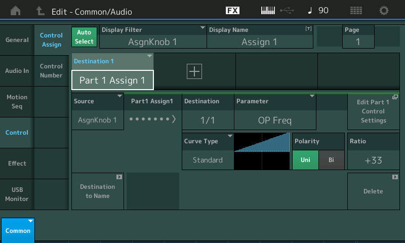
Literally, this means: Part 1’s Assign Knob 1 – which we know is “OP Frequency” (Modulator). As you turn the Super Knob you get the same result as we got previously when we turned the PART 1 Assign Knob 1, directly.
Next, let’s assign the PART 1 “EG LEVEL” (which we know is PART 1 Assign Knob 6) to Common Assign Knob #2:
- Turn Assign Knob 2, its name will appear in the DISPLAY FILTER: “AsgnKnob 2”.
- Touch the next “+” to ADD a CONTROL DESTINATION Assignment. It will be designated “Destination 2” as this is our second assignment.
“InsA Param 1” will appear by default. Touch that parameter name to view the POP-IN menu and your assignment options.
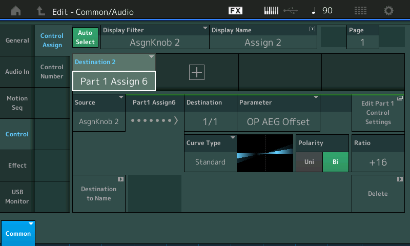
Select “Part 1” > “Part 1 Assign 6”, press [ENTER].
Literally: Part 1’s Assign Knob 6 – which we know is “EG Level” (OP AEG Offset) of the Modulator is now linked to the movement of Super Knob’s AsgnKnob2:
We have now linked two of the eight Part Assign Knob parameters to the Super Knob. Turning the Super Knob, or moving an FC7 pedal plugged into Foot Controller 2, will move the assigned parameters:
- Return to the HOME screen.
- Touch PART 1 to select it, so you can view the 8 Assign Knobs for PART 1.
Notice now when you turn the Super Knob (or move the optional FC7 plugged into Foot Controller 2) that Assign Knob 1 (Frequency) and Assign Knob 6 (EG Level) will move when the Super Knob is in motion!
We have linked Part Knobs 1 and 6 to the Super Knob-controlled Assign Knobs 1 and 2. This means when we turn the Super Knob, its Assign Knob position for Knobs 1 and 2 are in control of what happens to PART 1’s Assign 1 and 6 Knobs, respectively. Next, we can set a range of motion for the knobs.
Say we want to have the “Frequency” Knob sweep the entire range from 0 to 127, but would like the “EG Level” Knob to only increase from its stored condition of 80 through to 127. We can set up ranges for the movement of the Super Knob’s Assign Knobs. To be clear: We can restrict or limit the range of movement, even change the direction of movement, by setting the minimum and maximum values for the Super Knob’s 8 Assignable Knobs:
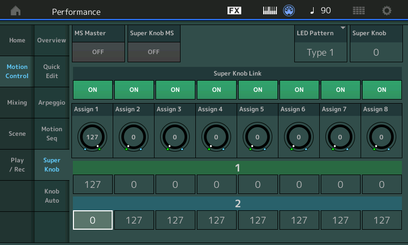
- From the HOME screen, touch “Motion Control”.
- Touch “Super Knob”.
- Here we can set the Super Knob controlled Assign 1 to full range: 0-127.
- And set Assign 2 range to 80-127:
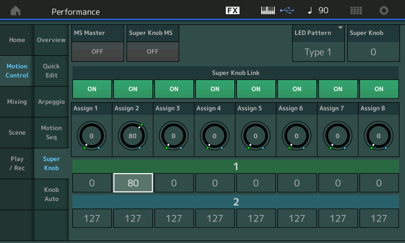
Now when you move the Super Knob observe (see and hear) the changes.
You can select whichever Assign Knobs you want and link them to the movement of the Super Knob. Some parameters make more sense than others to control via the Super Knob.
Reverse the Curse
Let’s reverse the application of FREQUENCY parameter by reversing one of the Super Knob controlled knobs. We’ve already seen that a parameters direction can be altered on the Control Assign screen by setting the Curve, Polarity, Ratio and Param 1 appropriately. Here we will take a look at reversing the application of the Assign Knob system.
Here’s how:
Navigate to the “Motion Control” > “Super Knob” screen:
- From the Home screen touch “Motion Control” located in column 1.
- Touch “Super Knob” in column 2.
Here you can see the 8 Super Knob linked Assign Knobs. We are going to reverse the direction of Assign Knob 1 by setting the VALUE 1 = 127 and the VALUE 2 = 0:
You can see that the KNOB now moves contrary to the others. Value 1 shown in green and Value 2 shown in blue. And likewise, the parameter now works in reverse. In our last installment, we learned that the application of the Controller can be customized on the Control Assign screen by using the CURVE TYPE, RATIO and even the parameter itself. There are many ways to accomplish the same function. Why? Because as you start to build your sounds or design your Performance PARTS you may want to link all parameters that move in the opposite direction to a specific Assign Knob. If, for example, we had another parameter we wished to reverse, we could link that parameter with COMMON Assign Knob 1.
Programming can get very involved (and you wouldn’t want it any other way) – as you go deeper and deeper into MODX you will discover that a single Knob can be doing multiple things to multiple parameter Destination each with a different scaling.
For more background on the Super Knob programming see the article here.
Explore and Experiment
We have included a BONUS download: Containing the PARTS we have studied combined – since P3 and P4 are ‘bookends’ and P1 and P2 are also ‘bookends’ – they complement each other so well. And together the random/alternate panning makes so much sense!
Performance, “P3-P4”, that combines the Parts P4 and P3 together. You will discover that they both are meant to work together. The Random Panning (hopefully you are listening in “glorious stereo” so that you can hear how they interact with each other). Assign Switches 1 and 2 will defeat the Reverb and Variation (delay), respectively, when activated. When performing these remember you can choose to either put all parameters in motion (Super Knob) or grab an individual parameter to control by directly addressing the knob. Again, we have named both the Common Assign Knobs and the individual Part Assign Knobs.
We also built a Performance, “P1-P2”, that combines P2 and P1 together. You will discover that they both are meant to work together, as well. Assign Switches 1 and 2 will defeat the Reverb and Variation (delay), respectively, when activated.
In our next installment in this series, we will look at Multi-Part AWM2/FM-X Performance that includes Arpeggios – and more. It will pull together much of what we have learned thus far.
Until next time. Enjoy!
In the meantime, join in the conversation about this lesson on the Forum here.
And if you need to catch up, check out the earlier lessons:
And if you are ready for the next lesson – Part 4 now available here!