
PERFORMANCE: Super Knob Values
(Performances used in the Mastering MODX Series are here)
In the previous examples the range and envelope of the modulations was set in the Part Control Box using the parameter Curve, Polarity and Ratio. Additionally, you can use another setting for shaping the modulation that is a bit more targeted. This is possible using the Super Knob Value 1 and Value 2 of the “Super Knob” window. The values are setting limits for the modulation ranges. (Basically, setting MINIMUMs and MAXIMUMs).
Please note: The Live Set that is used in the Mastering MODX series is located here.
If you have programmed a wide, or even the whole-range, for controlling a specific parameter in the Part’s Control Assign you can limit this range using the Super Knob Values 1 and 2.
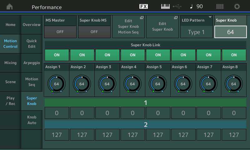
In the default setting you will find the Super Knob set to full range (0 – 127) for all knobs.
Stored value here is Super Knob = 64:
Limiting the range via the Super Knob Values might be easier than trying to find the intended ranges using only the parameter of the Part Controller Box. If you make rough settings in the Part Controller Box first, then you can do the fine adjustment of the range to be controlled in the Super Knob window with Value 1 and Value 2.
To be clear: It is not the range of the Super Knob itself that is limited with the Value settings that it will be changing. The Super Knob is still working for the complete range from leftmost to rightmost. Only the controlled parameter range of the target will get smaller or change direction.
You can use the example Performance 0008 “Super Knob Values” for checking the Value 1 + 2 function. It includes only one Part and one Control Set with the Destination LFO Speed of the chorus effect. This allows you to recognize the parameter changes very easily.
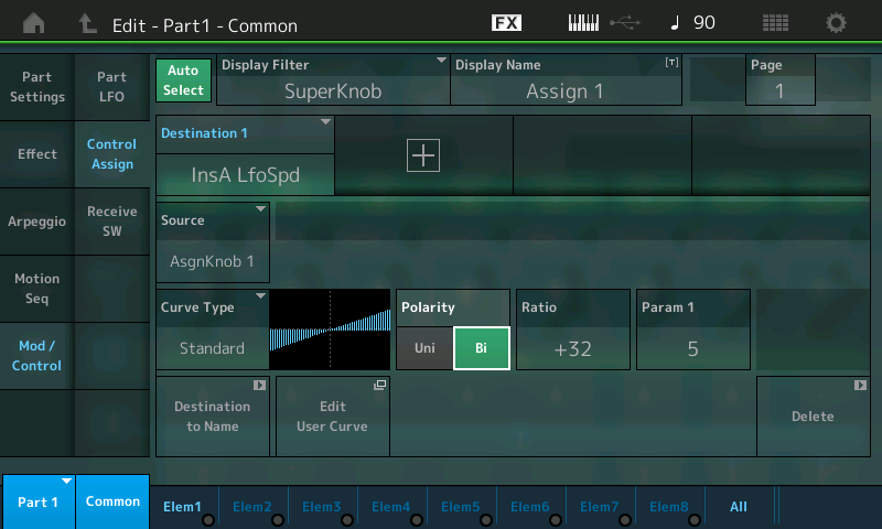
The settings in the Common/Audio and Part1 Controller Boxes are very simple and basically not different from previous examples:
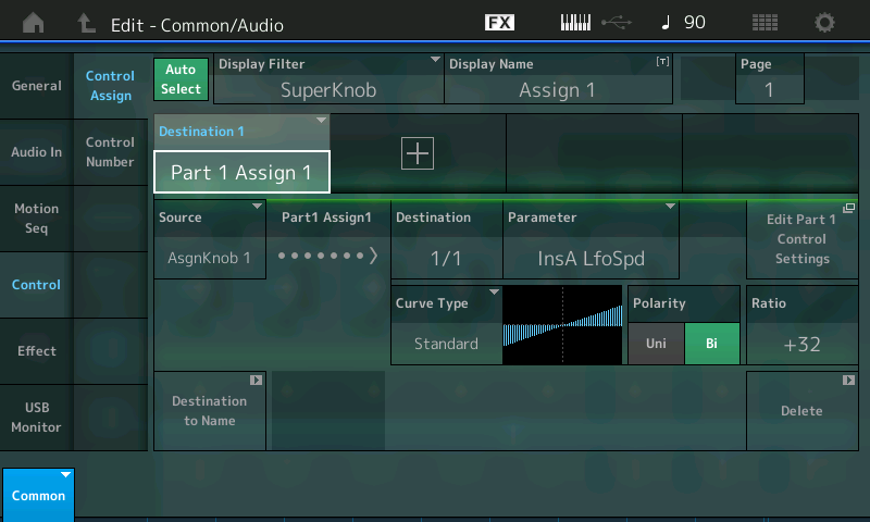
The CURVE is Standard; The POLARITY is Bi; the RATIO is set to +32, which enables full parameter control when the KNOB is moved minimum to maximum: Touch the box labeled “Edit Part 1 Control Settings” to view the actual Control Set.
Above the RATIO will determine “how much” change is applied… At +63 you hear the maximum speed of the LFO, at -64 you hear the minimum speed of the LFO, at +0 you hear the “stored value”.
For fine adjusting the controlled parameter range, now you can use Value 1 and Value 2 of the Super Knob window. Please change the default values of 0 and 127 to values, which are setting a useful control range – Here’s how
From HOME > touch “Motion Control” > “ Super Knob”…
Setting the Common Assign Knob 1 = 12 – 86, for example, would allow a control from a very slow chorus to a fast vibrato chorus. As you initially make the setting you may need to move the Super Knob to REFRESH its control over the parameter.
Green dot represents VALUE 1 and the blue dot is VALUE 2.
I have set the VALUE 1 to 12 and the VALUE 2 to 86
As you move the SUPER KNOB from its minimum position (7 o’clock) through its maximum position (5 o’clock), you will see that this parameter is only moving from a value of 12 through a value of 86 (with a Value of 49 in the center).
Please note: If you use the center position of the Super Knob as start position, the center position will no more correspond to the current parameter setting. In general, set the range for what you require, and STORE the PERFORMANCE with the Super Knob’s direct value wherever you desire/require.
For example: If the Values range is set to 32 – 96 the value of the center will not change, because the amount of decrease and increase is basically 32 on both sides of the center position. But in case of 12 – 86 the center position would change.
If you have any questions or comments about this article, please join us to discuss them on the Forum here.
Catch up on the previous article in the series – “Mastering MODX: Super Knob Complex” here.
Next article now available here: