

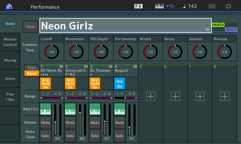
Even if this is not your kind of music, there is much we can learn from an exploration of these four MOTIF XF Voices (as Single Part MONTAGE) Performances. These four have been merged into “Neon Girlz”:
PART 1: 8Z Noize Xpress
PART 2: Universal AF1&2
PART 3: Da Thumperz
PART 4: Nyquist
In order to gain a better understanding of what is going on and how MONTAGE Multi Performances are built, we will explore each program individually, as SINGLE PART PERFORMANCES – then see how they are combined/merged into a single MULTI Performance. You will see that some parameters are sacrificed when you move to combine programs into a single entity – by studying the SINGLE PARTs separately we will be better prepared to understand how they change when “merged” with other PARTS. Also hearing what each PART is doing can often only be appreciated when you can hear their contribution isolated.
“8Z Noise Xpress“
Recall the Single PART Performance “8Z Noise Xpress” – Here’s how:
From the HOME screen:
– Press [CATEGORY SEARCH]
– In the Search box (with the magnifying glass) type in the letters: xpr
– This should be enough to find “8Z Noise Xpress”
– Touch the name in the CATEGORY SEARCH field to select it and then press [ENTER]:
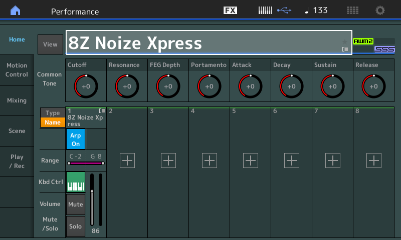
This is one of several so-called “8 Zone” Drum Kits – they are so named because of the unusual mapping of the Waveforms. Instead of using the typical 73 Element Drum Kit INIT as a starting point, which is setup to have one Waveform per Key, the 8Z Kits are built from the 8 Waveforms of a Normal INIT Part. There are several of these “8Z Kits” in the Factory Set – they are unconventional. The set of edit features of a Normal Part differ from those found in a Drum Part.
Exploring: There is a Drum Arp assigned to this “8Z Kit” so that you can hear how it functions when you play it with a standard Drum arpeggio phrase.
Press the [ARP ON/OFF] button to turn the Master ARP OFF, and play the PART manually using the keyboard.
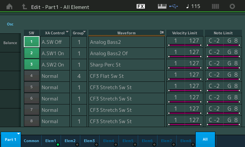
You will discover that the 8 Elements of the “Normal Part” are mapped as follows (see Note Limit column far right):
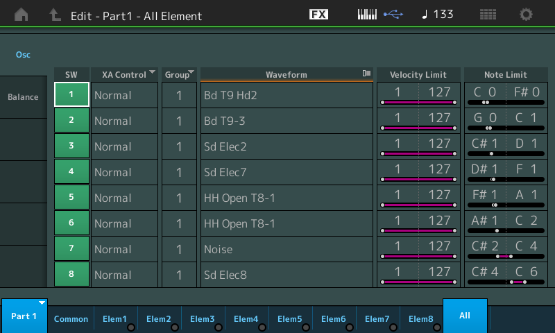
The principal drums (kick, snare, hihats) match the Keys of traditional drum map.
The SYSTEM EFFECTS (Reverb and Variation) for the SINGLE PERFORMANCE are “R3 Hall” and “Tempo Flanger”, respectively.
INSERTION EFFECT A – “Compressor/Distortion/Delay”
INSERTION EFFECT B – “Tempo Cross Delay”
The System Effects are standard Send/Return access for the entire Part (all Elements together), while the Insertion Effects are treated as part of the instrument construction (each Element can be routed to one, the other, both or neither of the two Insert blocks).
The OVERVIEW 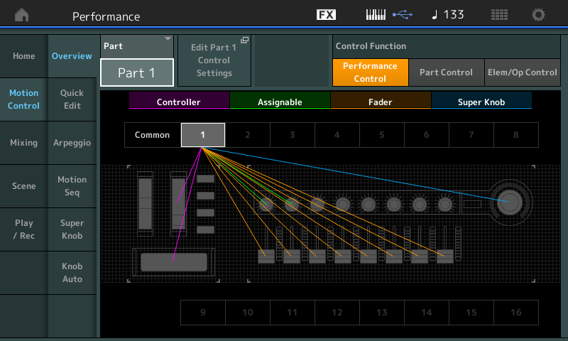
Overview of PART 1 Controllers shows that Assign Knobs 1 and 2, MW, Ribbon, Faders, and the Super Knob are engaged in this program:
Assign 1 – InsA OvrDrv (Comp/Dist/Delay)
Assign 2 – InsB Dry/Wet (Tempo Cross Delay)
MW – Var Send, InsB Dry/Wet, Volume (reduced)
Ribbon – InsA Dry/Wet
Fader – Each of the 8 Elements has its own Fader, 1-8
Super Knob – has Part 1, AssignKnob1 (InsA OvrDrv) linked to its movement via Common Assign Knob 1
In order to hear the ASSIGN 1 and ASSIGN 2 Knobs remember to select PART 1 and to activate the [ASSIGN] button before turning the Knobs. MW is sending the Drum Kit as a whole to the Variation Effect and adding a FLANGER effect, increasing send to the Tempo Cross Delay and lowering slightly the overall volume.
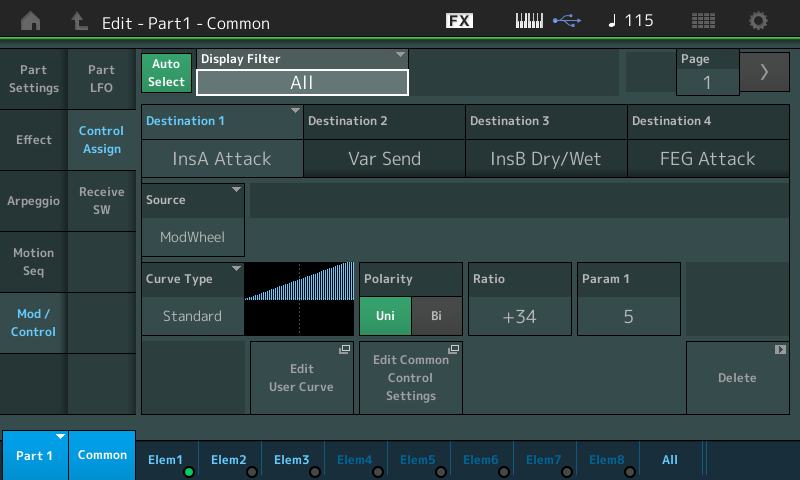
From the OVERVIEW of PART 1 (shown above) touch the shortcut box “Edit Part 1 Control Settings” to view the Control Assign screen.
Activate the “Auto Select” Function (green) so the Display Filter will show the Controller Assign for each Controller as you touch it. PART 1 Assign 1 is set control the Overdrive (InsA OvrDrv). If you press the upper [COMMON] button, to view Control Assign on this level, you can see the Super Knob’s Assign Knob 1 is linked to Part 1 Assign 1: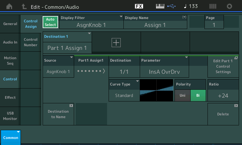
When [PART SELECT 1] is selected, and you have the [ASSIGN] function lit, you will observe the Super Knob, will indeed move Part Assign Knob 1. Remember, whatever is assigned and linked to the Super Knob will always be available, even if not selected. In other words – you no longer must select Part 1 in order to access its Assign Knob functions, at least not the ones linked to the Super Knob.
“Universal AF1&2“
Recall the Single PART Performance “Universal AF1&2” – this is actually four different synth bass tones; depending on the condition of the AsSw1 and AsSw2. The Assign Switches are not only available in the Control Assign matrix, they can be used as special “articulation” controls. When no Assign Switches are glowing brightly, you have the default Bass tone (Element 1 alone). When you latch Assign Switch 1, you have the Element 2 sounding. When you latch Assign Switch 2, you have the Element 3 sounding… and naturally when both Switches 1 and 2 are active you have the combination tone of Elements 2 and 3.
About the Assign Switches: The Assign Switches can be used in the CONTROL ASSIGN matrix, but they can also be used on the AMW2 Element “Osc/Tune” screen to determine when an Element is to be used. This funciton is the XA CONTROL or Expanded Articulation Control. Entire Elements can be activated and deactivated, while remaining sonically invisible (they do not glitch or interrupt audio – they can be used to make performance changes seamless, without detection). These “articulations” allows you, as performer, to change the behavior of the instrument sound – XA CONTROL includes normal, legato, cycle, random, key off, as well as the Element conditions A.Sw Off, A.Sw 1 On, A.Sw 2 On: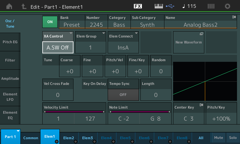
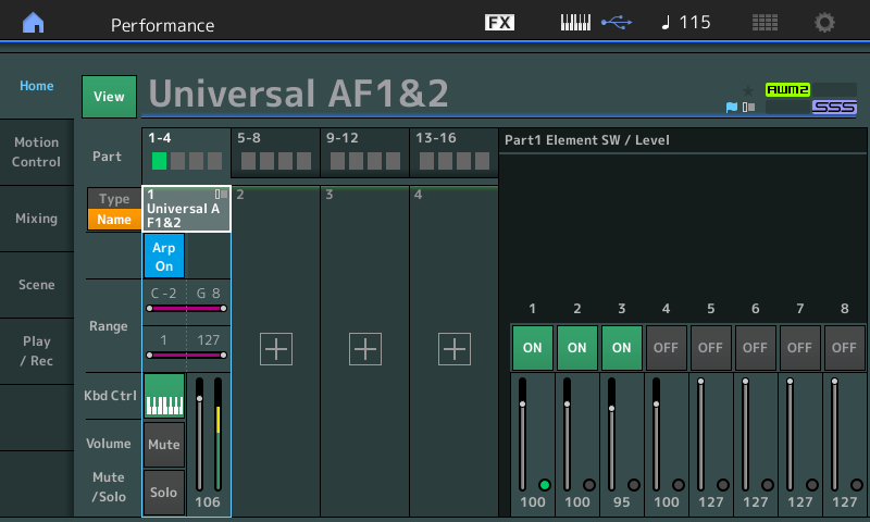
Here we will learn that there are two ways to view what Elements are sounding without having to decipher the NOTE and VELOCITY LIMIT settings.
Anytime there is a PART selected you can see an activity light for each active Element:
– Below on the right half of the screen, at the bottom, you can see that Element 1 is currently sounding. This would be the case when, according to the XA CONTROL (Xpanded Articulation Control) Element 1 is set to play when “A.SW Off” (only when both Assign Switch Off):
– INSERTION EFFECT A – “Classic Compressor”
– INSERTION EFFECT B – “Tempo Cross Delay”
“Da Thumperz“
Recall the Single PART “Da Thumperz” – here there are several types of movement within this complex sound. This PART utilizes Band Pass Filtering (BPF) to great affect. The Arpeggio is not only providing a rhythmic pulse to the notes triggered but additionally there is a “controller” message embedded within the arpeggio phrase that is controlling the PART’s Filter Cutoff (cc74). Within the synth engine there is also the PART LFO applying level to a Dynamic Phaser, applying Pitch variation and Cutoff Frequency movement of another kind, all Sync’d to the current Tempo.
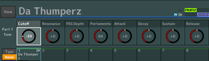
This CUTOFF knob is not a filter itself – it is applying an OFFSET. What this means is, it is adding and/or subtracting, to the Filters of the three Elements involved in this PART.
Filter Types: Exploring this PART is an excellent opportunity to discover something about the MONTAGE Filter section. It will reveal that the CUTOFF “Quick Edit“ Knob is offsetting the cutoff frequency of two 6dB/oct Band Pass filters (BPF6) on Elements 1, 2 and a 12dB/oct Band Pass filter (BPF12D) on Element 3 – giving the movement three distinct sweeps. Let’s take a look at the Filters involved. To view the Filters, we need to navigate to the Element level of the PART.
From HOME:
– Press [EDIT]
– Press [PART SELECT 1]
– Touch “Elem1” or the first button in row three on the right front panel (When in PART EDIT row three is Element Select, row four is Element Mute/Solo)
– Touch “Filter” > “Type”:
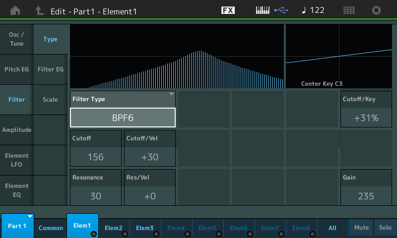
Much of the allure of analog synthesizers is the magic you can perform with the filter. In the engine here you have a variety of filter types at your beck and call (18 Filter Types in all). The Band Pass Filter TYPE is one that, literally, allows a band of frequencies in the middle range to “pass”, centered around the Cutoff Frequency. A severe drop off in sound is noticed both above and below this center band of frequencies that are allowed through. As the Cutoff Frequency moves it gives a very dramatic sweeping effect.
In turn, take a look at Elem2 and Elem3 to view each Filter and it’s settings. Element 2 is also BPF6, while Element 3 is a BPF12D. The number is the number of dB the signal is reduced on either side of the cutoff frequency per each Octave above or below. So a 6dB per Octave curve would mean for every Octave you go above or below the center Cutoff Frequency, the overall volume will be reduced by 6dB.
PART LFO and the Destination Box: The PART LFO, in this case, is controlling the movement of the Filter Cutoff Frequency, Pitch variation and applying a level offset to Insertion Effect B parameters (Dynamic Phaser). The PART LFO in MONTAGE (in Motif XF this was called the COMMON LFO) allows you to apply a Low Frequency Oscillator to three destinations and to scale the Depth on a per Element basis where appropriate. The routing options for control are any assignable parameter within the PART’s current Insertion Effects, in addition to Level, Pitch, Cutoff, Resonance, Pan or Element LFO Speed. The PART LFO can be sync’d to the TEMPO and can be set to musical values from a 16th note out to 16 quarter notes. It can be set as a one shot (acts like an envelope) or it can set to loop. The Phase can be set per Element which adds dimension to the movement:
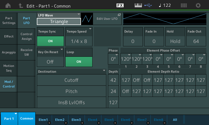
Learning to work the Destination Control Box is worth some time and experimenting. In this particular PART, the three selected DESTINATIONs (shown above) are “Cutoff”, “Pitch” and “InsB LvlOffs” (a parameter within Insertion Effect B). To begin your experiments with these parameters be sure the [ARP ON/OFF] is OFF. We want to eliminate all other movement so you can see/hear each of these settings in action.
Start by bringing the DEPTH of each of these three DESTINATIONS to “0”. Raise the MW a bit (also controlling the initial Cutoff Frequency) to an amount that lets you hear a good amount of signal when you trigger a chord – set MW about half way. Now experiment with each DESTINATION, in turn.
This Control Box lets you apply an overall DEPTH, and a DEPTH per Element (Element Depth Ratio) where applicable.
REMEMBER: This particular Part is just three Elements. You also can control the Phase. Phase will offset how the movement is initiated.
Here’s what this means:
The LFO WAVE = Triangle is the shape of application (shown at the top) – it starts from the centerline “0” and travels in a positive direction to its maximum at 90 degrees. It returns to a level of “0” at 180 degrees, reaches the minimum at 270 degrees and returns to “0” and starts again (see diagram in upper right corner). When you offset the movement of one of the Element’s Phase by 180 degrees, the Triangle shape would be inverted so that the wave travels in a negative direction first. Try setting Element 1, 2 and 3 to the same Phase then try different Phase values. Stagger the Phase values – hear the differences? The DEPTH amount will determine “how much” is applied. And while 127 does guarantee you will hear the movement – remember to use values in between – subtle sometimes is what you want.
Work with these until you are satisfied you hear what each is doing. By setting the other two Destinations to 0 you can concentrate on just one at a time. Experiment first with CUTOFF, setting the DEPTH to 127 for all three Elements, then try some other settings to see the dimension where you can give the movement. Return CUTOFF DEPTH to 0 and try PITCH. Initially the Element 1 DEPTH is “OFF” – try changing it for more dramatic movement. Then try the “InsB Level Offset” DEPTH to hear how the Dynamic Phaser is applied. The Dynamic Phaser will respond to velocity and Element 3 is set to respond to velocities 96-127.
Experiment by changing PITCH to PAN, as the DESTINATION, and work with the PHASE until you can hear how you can create a swirling stereo effect by offsetting the Phase of each of the Element’s relationship with the LFO. You can understand the Positive and Negative directions as moving Right from Center or Left from Center.
The LFO WAVE = Triangle is set to a TEMPO SPEED = “¼ x 8” or eight quarter notes (tempo = 122) and the movement is set to LOOP.
We should mention KEY ON RESET will allow you to select how the LFO behaves to touching the Keyboard. “OFF” will mean it is always happening. “EACH-ON” will mean each note-on will reset and restart the LFO, “1st-On” will synchronize the start to the first key pressed:
– The SYSTEM EFFECTS (Reverb and Variation) for this Single PART Performance are “R3 Plate” and “Tempo Cross Delay”, respectively.
– INSERTION EFFECT A – “VCM EQ 501”
– INSERTION EFFECT B – “Dynamic Phaser”:
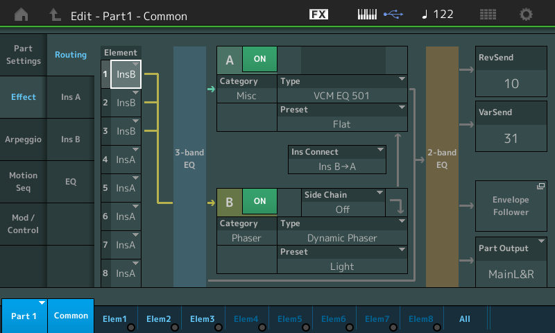
Above you can see the Element Routing through the MONTAGE Channel. The highlight is on Element 1 which is routed (along with Elements 2 and 3) to INSERT B. All three pass through the Part’s 3-band EQ before arriving at INSERTION block “B”. You can turn the “Dynamic Phaser” ON and OFF with the green switch (to hear its contribution). Between INSERTION blocks A and B you can see the “Ins Connect” parameter which determines that B is output to A. The VCM EQ 501 is a boutique grade 5-band parametric EQ – following the two Insertion blocks the signal passes through the PART’s 2-band EQ before the SYSTEM SENDS. You can drop in and EDIT the individual Insert blocks using the “InsA” and “InsB” touch boxes in column two of the screen.
As you can see routing within the PART is down to a per Element basis (in FM-X sounds it is the “Carrier” that can be routed through the system). The relationship between each Element and the Insertion Blocks can be setup so that each Element can be routed as you desire to one the other, both or none of the blocks.
“Nyquist“
Recall the Single PART PERFORMANCE “Nyquist”
This is a mono Synth Lead sound, made from two AWM2 Elements tuned to an interval of a musical 4th. An Oberheim Sawtooth combined with a Oscillator Sync Wave gives this an edgy tone. To isolate each of the two Elements, you would:
– Press [PART SELECT 1] Once you are in PART Select, remember: your right panel buttons row three and four allow you to select individual Elements and MUTE/SOLO those Elements, respectively.
– In row four the first two brightly lit buttons are Element 1 and Element 2. You can MUTE either one by simply touching its button to dim its light.
– The Oberheim Wave (Element 1) is your classic Sawtooth lead type sound.
– The Oscillator Sync (Element 2) is you classic nasal sync tone (tuned down a musical fourth).
– The SYSTEM EFFECTS (Reverb and Variation) for this Single PART Performance are “SPX Hall” and “Tempo Cross Delay”, respectively.
– INSERTION EFFECT A – “Compressor/Distortion”
– INSERTION EFFECT B – “VCM Flanger”
”Neon Girlz” Merged Parts: what comes along and what gets stripped away…
One of the ways MONTAGE PERFORMANCES can be made is by “merging” several Parts together into a Multi Part Performance. The act of “MERGE” is accomplished by touching the “+” symbol to ADD a Part or Parts to the existing Part or Parts. Beginning with a Single Part, “8Z Noise Xpress” you could “+” ADD, “Universal AF1&2”, then ADD “Da Thumperz” and finally ADD “Nyquist” to build the “Neon Girlz” four Part Performance. (For details on Category Search and the Merge function please review the following article “Using MONTAGE Category Search“.)
But obviously, there is more to it than just selecting the PARTS. The art of combining PARTS into a Multi PART Performance is finding some thing that makes them work together. Selecting the correct ARP Phrases is one important component but also you must work to build these PARTS into a cohesive program. In other words, you must make them work together. This means perhaps adjusting not only volumes, but EQ, and Effects so that they form a cohesive program. This is where we must explain what things are brought along when you combine (merge) and which parameters are left behind.
Each Part will naturally bring along its two Insertion Effects (as these are intricately woven into the instrument sound at the Element). Also brought along are all of the PART Control Assignments – again these are intricately woven into the fabric of the instrument.
What is not brought along is anything that was on the upper COMMON/Audio level of the Single Part. This includes the System Effects (the Reverb and the Variation), nor the Send amounts to those Effect blocks. Also not brought along are any Master Effect, Master EQ, or Super Knob relationships. And the reason should be clear – because we are now in a NEW Performance, all of those COMMON relationships are going to have to made here in this new Performance, (except for the very first Part that you start with – and you may opt to change them).
You will want to choose what SYSTEM EFFECTS work for all the PARTS to share, what Master Effect, and certainly what Master EQ. You can see that the EQ would necessarily be different because the multiple PARTS means any EQ from Single PART mode would not necessarily work for the PARTS you are “Merging” into this new PERFORMANCE. And so it is with all COMMON level settings – you will be making new PERFORMANCE COMMON settings.
Super Knob links, of course, would be removed because they rely on the Part number location and the Common Assign Knob they are linked to. It would be sheer chaos if all of a sudden another Performance’s links were plopped down in this new Performance. It is very likely they would make no sense at all – referring to locations that no longer are occupied by what was happening in the original program.
The System Effects are those belonging to the current Performance on a Send/Return basis, so you’ll need to select a Reverb and a Variation Type that all Parts can share via the Send controls on each Part.
You’ll also want to choose an appropriate Master Effect and dial in an appropriate Master EQ for this combination of instruments.
The PART Receive Switches will also need to be addressed once you have merged more than one Part to a Performance: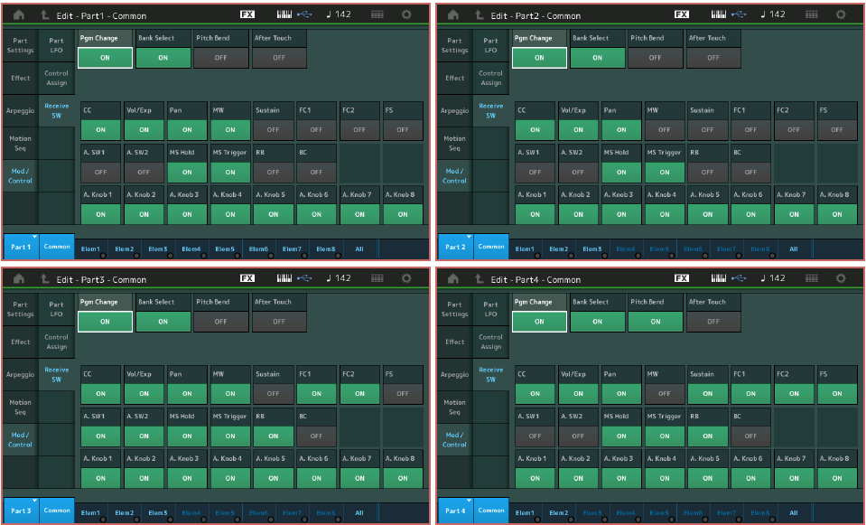
When playing a Drum Kit alone (as a Single Part) you don’t even think about PB, but as soon as you start building (merging Parts) you may need to consider what Parts you want to Receive the Pitch Bend message and which Parts you wish to ignore it entirely. Again, this is a consideration when transmitting to multiple Parts. If you are playing along with a lead, you may want it to be the only Part that Pitch Bends. Above you see the four PARTS and the settings as made for the original XF Performance “Neon Girlz”.
Now we should mention, what each Part does in response to a Controller is entirely up to the programming within the Part. It is totally possible to have the MW add vibrato to your lead, while opening the filter on a second Part, while Panning a third Part, etc. – the limits are truly your imagination. But the RECEIVE SWITCH page lets you customize whether the Part pays attention to that Controller at all.
Try it out – and enjoy Neon Girlz on your MONTAGE!
Questions or comments? Join the conversation about this article on the Forum here.
And stay tuned – more Motif XF Part conversions to come!
Download here: Neon_Girlz.X7B