

One of the most important usages of the Super Knob will be morphing (smoothly fading) between two, or more, different Parts. In this example Part 1 is using a Sawtooth wave, while Part 2 is using a Square wave. While Part 1 (Saw) is faded out, Part 2 (Square) is faded in.
The Sawtooth Wave is bright and buzzy – in includes all whole integer multiples of the Fundamental (all harmonics).
The Square Wave is the perfect case of the Pulse Wave where it is on 50% of the time and off 50% of the time – it is made up of only the odd numbered harmonics (3rd, 5th, 7th, 9th, etc.)
Listen closely as you morph from all harmonics (Saw) to just the odd harmonics (Square) and back – slowly turn the Super Knob from minimum-to-maximum and slowly return. You will continue to hear and identify the odd harmonics as you morph the Square Wave back into the Sawtooth. It is as if the Square Wave “hides” inside the Sawtooth Wave – and indeed by this morphing action we are changing the harmonic content of the sound, but in a very different way than you could do with Filter. A Filter works to remove all harmonics above (LPF) or below (HPF) a center frequency called the “Cutoff Frequency”. Use the screen “MUTE” buttons to isolate each Part, in turn, to convince yourself that you are actually turning the Sawtooth down as you turn the Square up.
The Assignment
The Controller matrix of the MODX is huge. This is why we are starting slowly. The Super Knob, on the upper Common/Audio level of the architecture, can have 16 parameter Destinations (1-16); Additionally, each Part can have its own 16 parameter Source/Destinations. The Super Knob, on the upper Common level of the architecture, can control its 8 Common Assign Knobs and each of the 16 Parts has its own 8 Assign Knobs. Huge!
Let’s begin by seeing how the Sawtooth Wave that we hear when we initially recall this sound, is turned down by the Super Knob, and the Square Wave in Part 2, which starts silent, is turned up by a single gesture.
Recall “Super Knob Morph A“
From the HOME screen (touch the Home icon in the upper left corner or press the [PERFORMANCE (HOME)] button)
- The cursor highlights the PERFORMANCE NAME: “Super Knob Morph A”
- Press [EDIT]
- Select the “COMMON” option (lower left corner of the screen appears in blue)
- In the screen select “Control” (left column of the screen) > “Control Assign”
- Make sure the “AUTO SELECT” option is active (green)
- Move Common Assignable Knob #1 to recall its settings
- Then Common Assignable Knob #2 to recall its settings
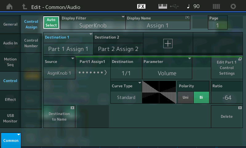
Here you can see that Common Assignable Knob 1: Destination 1 = PART 1 Assign 1; Source = AsgnKnob 1
Translation: The first Control Set has Common Assign 1 as the Source, and as it is turned by the Super Knob it will influence the parameter destination that is assigned to the Part 1 Assign Knob number 1.
Move Common Assignable Knob 2: Destination 2 = PART 2 Assign 2; Source = AsgnKnob 2
Translation: The second Control Set has Common Assign Knob 2 as the Source, and as it is turned by the Super Knob it will influence the parameter destination that is assigned to the Part 2 Assign Knob number 2.
You can view both of these assignments by touching the DISPLAY FILTER and setting it to “”ALL” or by moving the “SUPER KNOB”
The “Display Filter” simply changes what you are viewing at the current time.
As you move the Super Knob, with “Auto Select” active, you can review all parameters linked to the Super Knob.
“Destination 1” is the currently selected item (it’s blue). Move the cursor to highlight “Destination 2”. When you do it will be ‘selected’ and it will turn blue. Highlighting each assignment in turn will allow you to review “how” the controller movement is being applied.
You will observe the Curve indicates as you turn the Knob toward maximum (right) the Volume of Part 1 will decrease.
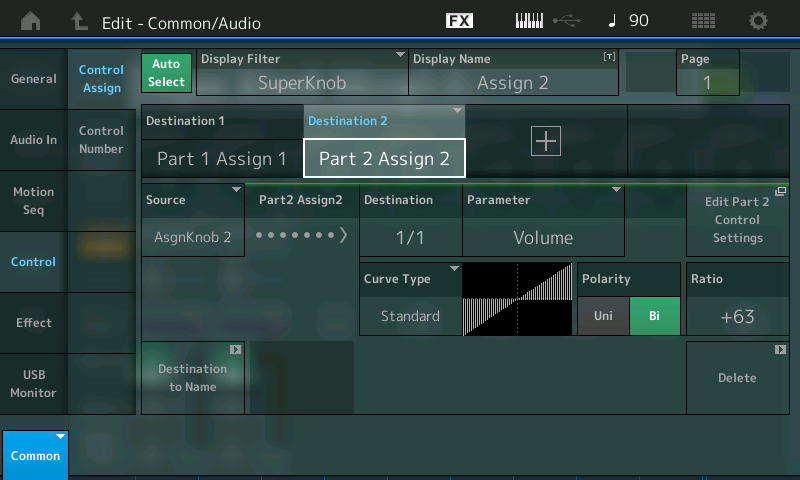
When Destination 2 is highlighted, you will observe that as the Curve moves towards maximum so does the Volume output.
After that the assignments in the individual PARTS can be made. You do so by dropping into PART EDIT.
Let’s view PART 1, first:
- Press the [PART SELECT – MUTE/SOLO] right front panel > Select PART 1
- The screen will read “Edit – Part1 – Common”
Press [EXIT] or “X” to close the overlay.
For Part 1 the Common Volume will be reduced using Polarity Bipolar and a negative Ratio, the following settings basically works well.
- We want to view the Assignment: “MOD/CONTROL” (left column of the screen) > “Control Assign”
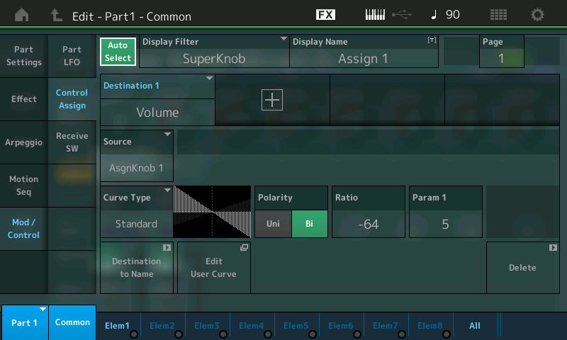
If you move SUPER KNOB you will see that:
Destination 1 = VOLUME
Source = AsgnKnob 1
Polarity = Bi
Ratio = -64
Param 1 = 5
The Curve graphic shows (reading left to right) the Volume is full and that as you turn up the SUPER KNOB this PART will be turned down in Volume.
Select PART SELECT 2
- In the lower left corner touch where it shows “PART1” for a pop-up menu and select “PART2”
- The screen is now: “Edit – Part2- Common”
Now when you move ASSIGN KNOB 2 you will see that:
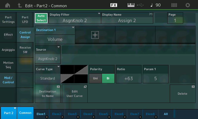
Destination 1 = VOLUME
Source = AsgnKnob 2
Polarity = Bi
Ratio = +63
Param 1 = 5
The Curve graphic shows (reading left to right) that as you turn up the Assign Knob 2, this PART, which starts at silence, will be turned up in Volume. In the minimum position you will only hear the Saw wave, in the maximum position only Square wave, in the center position a mix of both. These particular examples use the STANDARD Curve Type. This should be easy to follow, to hear and to understand.
Because both the Assign Knob 1 of PART 1 and the Assign Knob 2 of PART 2 are linked to the SUPER KNOB, moving the SUPER KNOB with “Auto Select” active, will show you these same two Controller boxes.
Return to the Main HOME screen.
Move the cursor down to select [PART 1] in the screen, move the Super Knob – observe the Assign Knob red indicator and value within.
Move the cursor to select [PART 2] move the Super Knob – observe the Assign Knob red indicator and the value within.
As programs get more complex – the “Display Filter” will be a very important tool. Because many things can simultaneously be linked to movement of a Knob or the Super Knob. The fact that the “Display Filter” can show you what is assigned to the Super Knob movement, this makes it much easier to sort through deeper complex Motion Control programs. For now, just recognize that the “Auto Select” function helps you *Filter* the data that is recalled to the *Display*. The “Display Filter” can show everything assigned to a specific SOURCE (Controller). And remember the SOURCE box is where you see the Controller assignment
Recall “Super Knob Morph B“
Basically the same with a few small changes: The Super Knob starts at 127 (fully clockwise) thus starting with the Square Wave, and morphs to the Sawtooth as you move counterclockwise. And the rate of change is different. Let’s see what’s going on:
From the HOME screen (touch the Home icon in the upper left corner):
- Highlight the PERFORMANCE NAME: “Super Knob Morph B”.
- Touch “MOTION CONTROL” in the screen just under “HOME”.
- Touch “SUPER KNOB” in the second column.
Here you can see that the SUPER KNOB is stored at a value of 127, effectively reversing its application:
- Touch “OVERVIEW” top of the second column to view the routing scheme.
- Change the “PART” from COMMON to “PART 1” to view the assignments to PART 1.
- Touch the box “Edit PART 1 Control Settings”.
This will take you directly to the PART 1 Controller setup… Now you can toggle between PARTs 1 and 2 using the blue PART [1] pop-up in the lower left corner of the screen.
Try manipulating the shape of the Curve by highlight “Param 1” and altering the value.
Notice how the application of the control is being altered by the PARAM 1 setting of “3” (for PART1) versus “7” (for PART2). These determine how fast one PART fades out and the other PART fades in:

By setting PART 1 to the CURVE created by “Param 1 = 3” and setting PART 2 to the CURVE created by “Param 1 = 7” creates a different crossfade – changing how long they overlap…
EXTRA CREDIT
Let’s experiment by checking out using different Curve Types for getting a slightly different morphing process – because PART 1 has a Negative RATIO and PART 2 has the Positive RATIO, you can create these interesting mirror images with the CURVE TYPES:
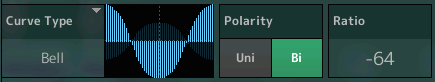
For example, set the CURVE TYPE = “BELL” shape with opposite positive/negative RATIO settings for the PARTs;
Set PART 1 (Sawtooth wave) to RATIO = -64 (above)
Set PART 2 (Square wave) to RATIO = +63 (below)
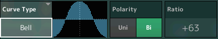
This allows you to get the Sawtooth wave at the extremes (top graphic) and the Square wave only in the middle (bottom graphic) of the Super Knob travel.
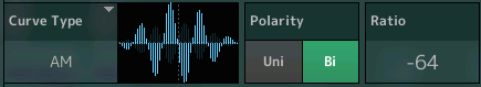
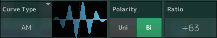
Another example, the “AM” shape with opposite positive/negative RATIO settings, allows you to switch alternately between Saw and Square as you turn the knob from minimum toward maximum
NOTE: Navigating back and forth may, at first, seem to be a chore (because you must select the PART and then move the KNOB in order to view what you want) but as you begin to recognize that each PART has its own set of functions the power of this is revealed. Spending time navigating and experimenting here will be well rewarded as you get used to just how deep “scuba diving” with MODX can get! This is the first big step into the MOTION CONTROL SYSTEM.
Recommended: For example, the STANDARD Curve Type selection would work a bit more smoothly. Set the RATIO = -32 and +32 for the respective Parts 1 and 2, using the Bipolar CURVE TYPE for both. Set the PARAM 1 = 3 for PART 1 and PARAM 1 = 7 for PART 2. This PARAM (will change the CURVE TYPE structure. The graphic gives you a good indication of what is actually happening). Explore the PARAM 1 settings to see how it changes the curve.
At the RATIO’-32′ and ‘+32’; and both set as PARAM 1 = 5, you still get a bit of the PART that fades out when you reach the extremes – instead of silence from the faded PART at the extreme
For Part 1 (fade out of Saw wave) you could use alternately polarity Unipolar with a Ratio of 32, which works especially fine if the Super Knob starts with left position.
If you have any questions or comments about this article, please join us to discuss them on the Forum here.
Catch up on the previous article in the series – “Mastering MODX: Super Knob Bipolar” here.
Next article: “Mastering MODX: Super Knob Complex” here.