

Manny’s FM-Xplorations Article 1
In this article series I’m going to dive into what’s unique about the MONTAGE FM-X synthesis engine, ways to approach programming your own sounds from scratch, how to utilize the realtime control using the Assignable Knobs, SuperKnob, Scenes and Motion Sequences – as well as cover some unique tips, tricks and quirks of FM-X programming. As in my article series “Manny’s Modulation Manifesto” for Reface DX I’m going to avoid the “FM Math” discussions that so many find a stumbling block in learning FM programming. Instead the focus will be on on tutorial examples that allow you to train your ear on “how” certain parameters change the sound, not the complexities of “why.”
If you feel you’re a beginner who might be worried about diving into something as deep as FM-X and would like a more gradual introduction to FM synthesis, I recommend you read the “Manny’s Modulation Manifesto” article series on YamahaSynth.com as it covers the introductory FM basics addressed more to those with minimal FM experience applied to the simpler Reface DX FM engine.
Alrighty then! Let’s talk about FM-X synthesis and what makes it different compared to the other types of FM with which you might be familiar. The biggest difference right off the bat is how many Operators there are — eight! The unique FS1r notwithstanding, Yamaha’s prior FM engines typically had four or six Operators. Having eight Operators opens up a lot more unique algorithm possibilities for the creation and control of more complex harmonic structures. In addition, each of the Operators have six additional complex waveforms available in addition to the basic sine wave Operator of the original DX7.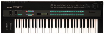 Although Yamaha has made FM synthesizers with additional non-sine wave Operators before, there’s a significant difference with the MONTAGE and FM-X. The difference is that these waveforms are variable – meaning they can be changed in real-time. To top it all off, there is a versatile multi-mode filter and powerful Effects processing available which are also controllable in realtime. Though I will sometimes utilize the filters and Effects within the accompanying tutorial Performances for this article series, my detailed focus will be on the FM components of sound design.
The first thing is to load up the example Performances that will be referenced throughout this article series. The file “Manny FMXplore” is at bottom of this page to download and load into your MONTAGE.
Now we’re ready to first get familiar with and explore the building blocks of FM-X, the Operator Spectral Waveforms. Go to the Live Set Bank “MannyFMXplr” and load the Performance “Init Normal (FM-X)” then exit to the Home page. Go into Part Edit mode and select the Form/Freq page for Operator 1: 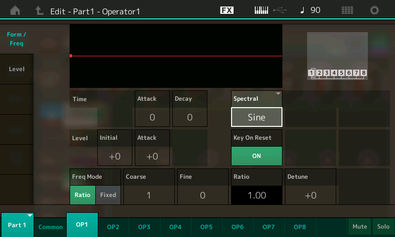
This initialized Performance has the waveform Spectral shape set to Sine. Let’s change the Spectral shape from Sine to All1 and initially you’ll notice there’s basically no change in the timbre. So what is going on? With FM-X, each Operator has the ability to “filter” the non-Sine Spectral Waveforms controlled by two parameters – Skirt and Resonance.
We’ll start with Skirt. The Skirt parameter is very similar to the cutoff of a low pass filter, so when the Skirt value is zero it is similar to the filter being fully “closed” so very few if any overtones are being heard. Now start increasing the Skirt value and you will begin to hear all the overtones present in the waveform, very similar to raising the cutoff frequency of a low pass filter. When set to the maximum value of 7, all the harmonics in the waveform will be heard, like the filter is fully “open.” With the All1 waveform this is a sawtooth type wave.
Now go back and select each of the different Spectral Waveform and increase/decrease the Skirt and listen to the timbre differences of each. The non-Sine Spectral Waves available are All1, All2, Odd1, Odd2, Res1 and Res2. The All1 and All2 waves are two variations of the harmonic structure of a sawtooth wave, meaning all the integer overtones are present. The Odd1 and Odd2 waves are two variations of the harmonic structure of a square wave, meaning only the odd numbers overtones are present and you have the ability to control the Skirt parameter for these waves.
The remaining Res1 and Res2 Spectral Waves have all the integer overtones present like All1 and All2, but in addition to the Skirt parameter they have the added ability to emphasize a specific overtone with the Resonance parameter. To hear this let’s start by selecting the Res1 wave. As you increase and decrease the Skirt parameter (leaving the Resonance parameter at zero) you’ll hear the timbre is somewhat similar to the All1 wave. Now, set the Skirt to zero start increasing the Resonance parameter. You’ll hear a specific overtone in the Res1 wave become greatly emphasized – beginning with the first overtone when Resonance is set to zero, all the way through the harmonic series of overtones. You may notice in the range of 0-6 it sounds similar to playing with organ drawbars. Play low notes on the keyboard to hear the full range of Resonance parameter. Now, go back and do the same changing of the Resonance values at different Skirt settings and listen to the difference in the timbral changes.
Now that you have been introduced to the “raw” Operator building blocks available, let’s have a quick review of what FM is all about. FM synthesis creates complex timbres (harmonic structures) by modulating one Operator with another (or multiple) Operators in an arrangement called an Algorithm. The resulting timbre (harmonic structure) of our sound is determined by a combination of the Frequency Ratios of the Modulator and Carrier Operators, the modulation amount (Modulator Level) and the harmonic structure of the Operator waveforms themselves. Carrier Operators – those on the “bottom” row of the Algorithm – are the ones you directly hear. Modulator Operators you can’t hear directly, but you do hear the harmonic content they create based on their interaction with the Carrier as determined by their aforementioned Level, Ratio and waveform — the Spectral, Skirt and Resonance — settings.
Another way to put it, the final resulting harmonic structure is determined by the Ratio, Spectral Waveform and Resonance settings. The brightness, or loudness, of the overtones in that harmonic structure is controlled by the Modulator Level, Skirt and Feedback.
I mentioned the famous — or infamous! — Algorithm. Algorithms specify the number and arrangement of Carrier Operators and Modulator Operators. Operators can be “stacked” (in vertical arrangement): 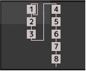
“Branched” (in horizontal arrangement): 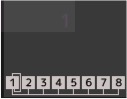
Or a combination of both: 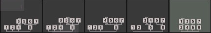
Branched Modulators are fully independent in their control of and their contribution to the final timbre of the Carrier they modulate. Stacked Modulators have shared control of, and contributions to, the final timbre of the Carrier they modulate. It’s easiest to hear what is going on with a single Modulator interacting with a single Carrier – so that’s where I’m going to start with our first tutorial example.
Select the Performance “Manny Mod Tutorial 1” from the Live Set and exit to the Home Performance page: 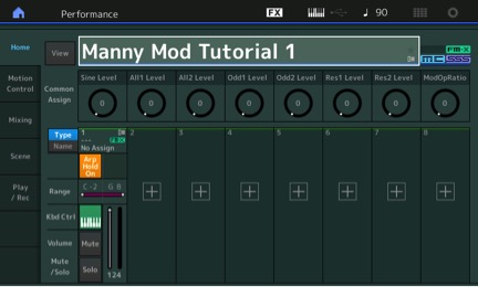
To easily show the basics of how the FM-X Modulators create and change the sound (timbre), I’ve set up assignable controllers programmed to the core FM-X parameters within this Performance. We can quickly hear how these parameters change the sound without having to navigate through the Edit pages. You can see the first seven Assignable Knobs directly control the Level (modulation index or amount) for each one of the seven types of Operator Spectral Waveforms. The eighth Assignable Knob controls the Modulator Frequency Ratio. In addition, the Ribbon controls the Feedback for the Sine Wave Modulator as well as the Skirt parameter for the other Modulator Waveforms. The Pitch Bend controls the Resonance parameter for the Res1 and Res1 Modulator Waves. Finally the Mod Wheel controls the Ratio of the Carrier, which has its Spectral Wave set to Sine.
When you first play the Performance, all you will hear is the plain sine wave of the Carrier. This example with the basics of the one Carrier and one Modulator sine wave FM pair. Start increasing the amount of Assignable Knob 1 to hear how the sine wave Modulator changes the sound as you increase the Modulator Level. Move it up and down a few times and listen to the changes. Play with the Ribbon to see how increasing/decreasing the Feedback of the sine wave Modulator changes the sound. Next, set Assignable Knob 1 to a value of 96 and touch and hold the Ribbon at the far right side — you should hear the classic FM sawtooth wave created by the Modulator and Carrier Ratios of 1.00 and maximum Feedback. Leave Knob 1 at 90 and we’ll now go to Assignable Knob 8 to change the Ratio of the Modulator to create a different harmonic structure. The range of this knob is set to step through Ratios 1 to 8, with Ratio 1.00 when the Knob is at a value of 0; Ratio 2.00 at a value of 16, Ratio 3.00 at a value of 32, etc. changing to the next integer Ratio every value increment of 16 until it maxes out at Ratio 8.00.
Let’s start setting the Knob value to 16 for a Ratio of 2.00. Again, touch the Ribbon at the far right. You should hear the classic FM square wave created by the Modulator Ratio of 2.00 and the Carrier Ratio of 1.00. Go back and move Knob 1 up and down and again listen to the changes in the sound as the Modulator Level changes and also remember to play with the Ribbon to hear the effect of Feedback. Continue to adjust Knob 8 to hear the harmonic structures created as the Modulator Ratio changes all the way up to 8.00 as you try different setting of Knob 1 and change the Feedback using the Ribbon.
Now that you’ve heard the classic sine wave based FM, let’s hear what happens with the additional FM-X Spectral Waves of All1, All2, Odd1, Odd2, Res1 and Res2. First turn Knob 1 all the way down. Then starting using Knob 2 and repeat the process in the previous paragraphs individually for each of the All and Odd Spectral Waveforms using Knobs 2 through 5. For these waveforms, the Ribbon controls the Skirt parameter, which you will hear sounds somewhat similar to Feedback. Both parameters offer different ways to create additional harmonic intensity or brightness in our sound and behave differently from increasing the Modulator Level. Remember to change the Ratios of each of these Modulator waves using Knob 8 as we did with the Sine example above.
Now we’ll move on to the Res1 and Res2 waveforms. Make sure all Knobs are reset to zero and raise Assignable Knob 6 for the Res1 wave to a value of 64. First, let’s slowly move the Pitch Bend wheel down and up to hear how different Resonance settings change the sound. Remember the two Res waves have all the integer harmonics (overtones) present, but with a specific overtone emphasized based on the Resonance parameter value. When the Resonance is at Zero (Pitch Bend all the way down) the first overtone is emphasized; with the Pitch Bend in the middle, the Resonance is set to 7 and the eighth overtone is emphasized. The Pitch Bend range is set to go up to a Resonance of 14.
Next, play with the Ribbon to hear how the Skirt causes brightness changes and notice the effect is less pronounced in the Res waves compared to the All and Odd shapes, especially as the Resonance value gets higher. Next, let’s change the Modulator Ratios again using Assignable Knob 8. Play around with Knob and the Pitch Bend together to hear how Ratios and Resonance interact Repeat it all for the Res2 wave on Knob 7 This may all seem tedious at first, but do take your time and listen to the changes with all the combinations. As I mentioned at the beginning of this article (and emphasized in my reface DX articles), the goal is to build your “ear experience” to be familiar with “when I change that parameter, this changes in the sound” — meaning learn “how” the sound changes with different Modulator Levels, Ratios, Spectral Waveforms and Feedback, Skirt, Resonance, etc. It’s not so important to know the math details and the “why” all the changes occur because at the end of the day it’s your ears that determine you created a sound you like.
So that said, there’s still – more!
We’ve only listened to changing the Ratio of the Modulators. Time to go back and do it all again, but now also change the Carrier Ratio by moving the Mod Wheel. As with Knob 8 for the Modulators, the Mod Wheel is setup to change the Ratio from 1.00 to 8.00 for the Carrier. Then go for it and randomly move everything around!
One way to make this a little more fun is to turn on the Arpeggiator. I’ve set up 6 Scenes with different patterns and the Arpeggiator set to Hold mode. You can trigger an Arpeggio then use both hands to tweak the Knobs, Ribbon, Pitch Bend and Mod Wheel in all sorts of combinations, showcasing what MONTAGE and FM-X is designed for — sophisticated dynamic control of your sound. Go crazy and create some haxidents!
I know all that knob twiddling may read a little bit confusing, so make sure you watch the video “Manny’s FM-Xplorations Tutorial 1” parts 1 & 2 below to see and hear the above example in detail.
Finally a “Secret Bonus”: The Assignable Switches are set up to change the Spectral Wave and Skirt of our Carrier Operator 8. With only Switch 1 active, the Spectral Wave will change from Sine to All1. With only Switch 2 active it will change to Odd1. With both Switches 1and 2 active it will change to Res1. And as before, the Ribbon controls the Skirt and Pitch Bend controls the Resonance. So play around and tweak all the Knobs, etc. with different combinations of the Switches active.
Wrapping up, we started covering the basics of the FM-X waves and core FM Operator parameters of Ratio, Spectral Wave, Skirt, Resonance, Feedback and Modulator Level. We finished with manual realtime control of these core parameters. Next time we’ll look at using Envelopes controlling Modulator Levels to shape the behavior of our sound, as well as introduce using Scenes and Motion Control to control FM-X parameters. Until next time, happy tweaking!
FM-X Tutorial Video Part I:
M-X Tutorial Video Part II:
* Another special treat for those who want a little more technical detail on how this Performance was created: I used seven separate Modulators for the seven Spectral Waveforms, so I used Algorithm 68: 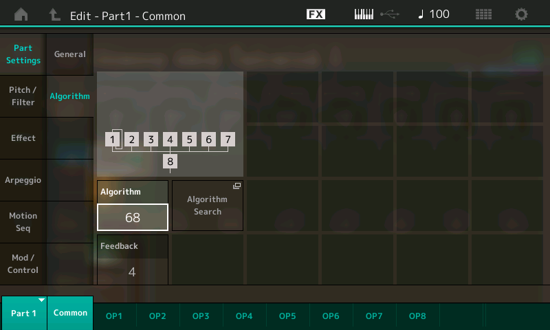
This algorithm has Operator 8 as the single Carrier and all the Modulator Operators 1 through 7 each separately modulate the Carrier in a 7 Operator branch. As I mentioned before, in a branch arrangement of Modulators their Levels individually interact with the Carrier thus I was able to have independent control of how much each of the 7 Spectral Waves alter the final sound by using the Assignable Knobs to control the Level for each Modulator. Because I ran out of Knobs controlling the Modulators, I chose to use the Mod Wheel for the control of the Carrier Ratio as you can set and leave it at a value just like a Knob. Since both the Ribbon and the Pitch Bend are always at their “50%” position unless you’re actually moving/touching them, I chose to set the default values for the Operator Skirt and Resonance to “middle” values and use bipolar modulation of them from the Ribbon and Pitch Bend respectively to achieve the range that they control those parameter values.
Questions/comments? Join the conversation about this article in the series on the Forum here.
Ready for Part 2? Now available here!
Download the library filefor all the Performances referenced in the article series here: MannyFMX