

Tagged Under
Let’s begin our look at the Super Knob with a basic assignment on the uppermost level of the Performance architecture. The MODX has two levels of programming: COMMON – which as the name implies is parameters that affect things overall. And PART – which are parameters concerning an individual PART of a Performance.
The upper COMMON level affects all Parts in common – no matter how many Parts were added. We will use a single PART Performance to keep things simple. But recognize if additional PARTS were added to this Performance they could be affected by these COMMON level settings. This is a very simple Super Knob programming example using just two Effect parameters.
What you will learn here is how the Super Knob can be used to change multiple parameters. Some of the Factory Performances are so complex it is often difficult to decipher exactly what is going on. We will learn to explore an existing program that focuses on a single basic concept – and while these may not be the most remarkable synth sounds, we will use them to clearly explain a programming concept. It is assumed you are navigating the screens as we explore. As we progress we will introduce several of the useful “shortcuts” to navigating the firmware.
In MODX, the architecture is divided into two segments: Common (overall) and Part (individual).
Example #1: “Super Knob Common”
In this particular program a Sawtooth Wave is being used. The Variation Effect being applied is a Chorus Type called “2 Modulator” (dual modulation). Hit and hold a note you will hear the undulating sound of the dual chorus. A very simple programming change occurs as you move the Super Knob from minimum-to-maximum. You hear the Speed increase but something else is happening, as well. The amount (Depth) is decreasing as the Knob is increased.
New Terms and Concepts: The Super Knob automatically controls the eight Performance Common Assign Knobs, 1-8. No special assignment needs to be made to have these upper level functions respond to the Super Knob – this is the default. When you turn the Super Knob, the 8 Common Assign Knobs, 1-8, are initially ‘linked’ to its movement and they all will move in concert, 0-127. You can see that here:
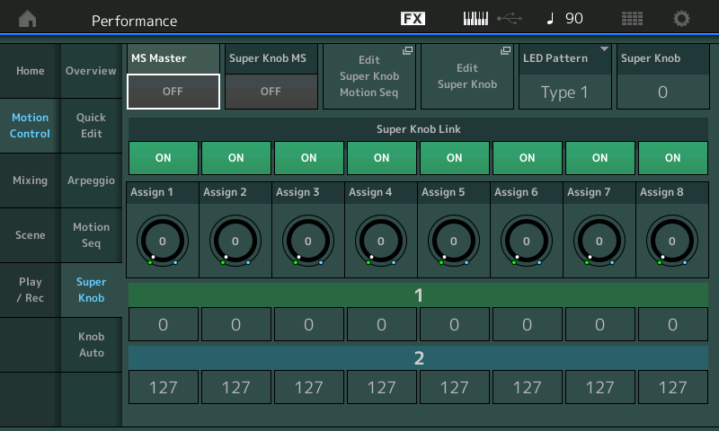
From the HOME screen, touch “Motion Control” > “Super Knob”. It is here that the default “Super Knob Link” between the 8 Common Assign Knobs and their range (0-127) exists. Turn the Super Knob and observe the above screen. The Knobs move from the green dot (minimum) to the blue dot (maximum).
What they are assigned to do, exactly, and how they move, as we will see, will depend on the deeper levels of programming.
The Super Knob, typically, sends minimum value (0) when fully counterclockwise (at 7 o’clock) thru to maximum (127) when fully clockwise (at 5 o’clock). The green (1) value is minimum and the blue (2) value is maximum, by default.
New Terms you will encounter:
Polarity = Uni (Unipolar) describes a parameter that moves in just one direction and back, as in a minimum value moving toward a maximum value and back from a maximum toward a minimum. You can change from here to there and back again. This is described as “unidirectional” motion. “Uni” is the polarity that is used in our first example.
Ratio Applying a positive Ratio will increase, while applying a negative Ratio will decrease the parameter value. Ratio is a comparison between two items and in this case represents the DEPTH of application. How it is, and how it changes.
Curve Type is a parameter that allows you deeper control over the application of modulation/change. In the first examples, we’ll limit ourselves to the “Standard” Curve Type (linear), which is very easy to hear and understand.
This is a very simple Super Knob programming example using just two System Effect (Common) parameters. The “concept” is the important thing here: We will be increasing one parameter and at the same time decreasing another parameter.
SYSTEM EFFECTS = Reverb and Variation
Like its predecessors, the MODX has “shared” Effects using a Send/Return type scenario (called the “System Effects”) and each PART has access to them. The shared System Effects would be considered among the COMMON parameter settings – because they are available to all PARTS via an AUXILIARY-type Send/Return situation; just as you would find on any professional mixing console. There are two SYSTEM EFFECT processors. One is called “Reverb” – it provides the overall acoustics of the virtual room for your instrument ensemble; and the other is called the “Variation” which provides a variety of time delay and other types you might wish to apply to several music parts.
In this example, the Variation Effect is assigned to a Chorus type called “2 Modulator” (a dual chorus effect that was extremely popular back in the 1970s-80s). Any PART with the Variation (VAR SEND) amount turned up will be sent to this dual chorus effect and therefore, the changes assigned here would be applied to all the Parts using the Variation Effect, in common.
The Variation Effect parameters we will be controlling are: LFO Speed (Low Frequency Oscillator speed) and PM Depth (Pitch Modulation Depth). These are assigned to the Assignable Knobs 1 and 2, respectively.
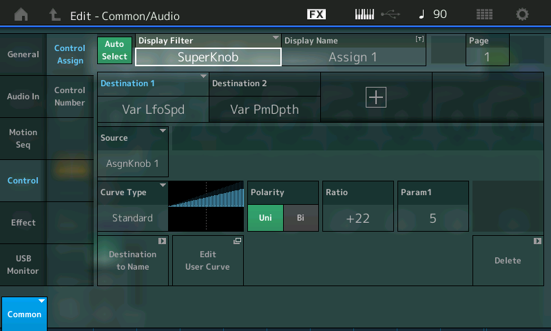
The assignments are made on the “Edit – Common/Audio” > “Control” > “Control Assign” screen. The very top line in the screen will always identify exactly where you are “Edit – Common/Audio”.
Let’s navigate there using the front panel buttons:
From the main HOME screen
- When you are “HOME” the PERFORMANCE NAME is highlighted: “Super Knob Common”
- Press [EDIT]
- “Common” is selected in the lower left corner of the screen (blue); You arrive at the “Edit – Common/Audio” edit screen.
- The top line of the screen will always identify “where” you are:

- In the screen touch “Control” (the left column in the screen) > then in second column select “Control Assign”
- Make sure the “AUTO SELECT” option is active (green). Touch it to activate/deactivate. This allows you to touch/turn/move a controller to immediately access its parameters in the screen. “Auto Select” works with the adjacent “Display Filter” box to show you the selected controller and all that is assigned to it.
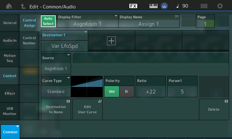
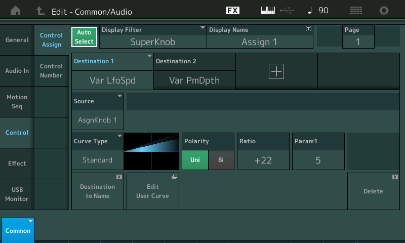
- Move ASSIGN KNOB 1 to immediately view its assignment. (Var LfoSpd) “Variation Low Frequency Oscillator Speed”. See screenshot below. (If you ever have a problem deciphering the abbreviations, please refer to the “Synthesizer Parameter Manual” (PDF)).
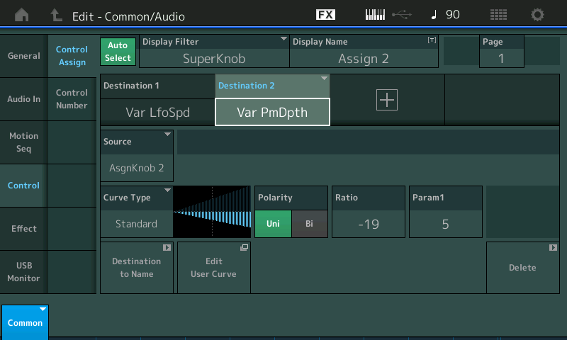
- Move ASSIGN KNOB 2 to view its assignment (Var PmDpth) Variation Pitch Modulation Depth. See screenshot below.
If you do not see this screen make sure your [ASSIGN] button, located just to the left of the four Knobs is lit.
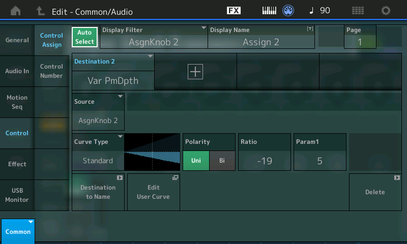
The Polarity setting in each is Uni (Unipolar). You can see that one has a Curve showing increase (a positive Ratio value) while the other has a Curve applying a decrease (a negative Ratio value).
As you turn a Knob clockwise the graphic is read left-to-right.
- Turning Assign Knob 1, directly, you hear the Speed of the LFO increasing.
- Turning Assign Knob 2, directly, you hear the Depth or amount of modulation, decreasing.
- Turning the Super Knob, we know, turns both Knobs simultaneously _ due to the Super Knob Link.
This means as you turn the Super Knob up, you are increasing the SPEED of the LFO, but simultaneously you are decreasing the DEPTH (amount) that is being heard. By working these two parameters together we can tailor the response of the change of Speed. As it gets beyond a certain value – perhaps it becomes none useful from a musical standpoint. We can decrease the amount heard before that happens!
EXPLORE
To fully understand this, next, we will navigate to within the Variation Effect and find the parameters being offset.
From the “Edit – Common/Audio”:
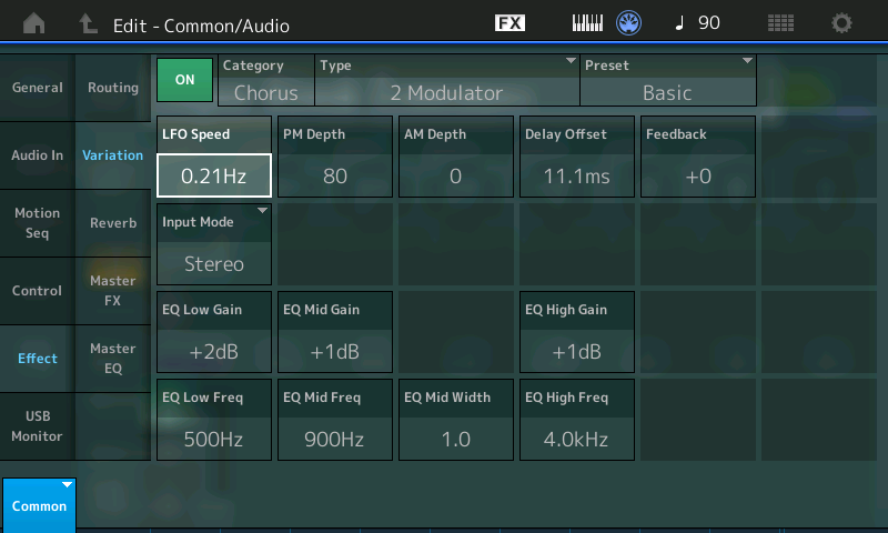
Touch “Effect” > “Variation”
LFO Speed = 0.21Hz
PM Depth = 80
“LFO Speed” – Low Frequency Oscillator Speed. The Chorus effect has a slowly undulating quality. This movement is handled by the Low Frequency (slow speed) oscillator. This controls ‘how fast’.
“PM Depth” – Pitch Modulation Depth, is what musicians refer to as vibrato – pitch modulation is the change in tuning above and below a center point. The Depth is ‘how much’.
The Assign Knobs are applying an “offset” to the originally stored value. You can hear as you turn Assign Knob 1 that the speed of modulation increases dramatically, as you turn clockwise, and returns to the slowly undulating quality when you return it to minimum.
The parameter value is not 0, rather, it starts at the value as set, and is offset from this value by the Knob movement. Therefore, you can anticipate that when turning the Knob assigned to control the value change, it begins with the ‘stored value’ and is offset from that position. Assigning control does not have to mean absolute minimum to absolute maximum, we can start at the ‘stored value’ and when we apply our controller, you will hear the change. This means assigning control does not mean that everything must start at ‘off’ and run the full range that the actual parameter moves – you can ‘scale’ the control knob movement to a precise range. Another important concept.
When the Super Knob is at minimum (fully counterclockwise) the “LFO Speed” is equal to the ‘stored value’, which we can now see is “0.21Hz” and the “PM Depth” is 80. (Screenshot below)
Highlight and adjust the LFO Speed parameter directly to hear its adjustment to the speed of modulation from a minimum of 0.0Hz to a maximum of 39.7Hz. You can do so by highlighting the parameter in the Variation Effect screen (shown above) and use the Data Dial (just to the right of the screen) to change the actual setting value. The entire range travels from 0.0Hz through to 39.7 cycles per second.
Notice the profound change in the sound as you reach 0.0Hz. If you listening in stereo (and you should be) you will suddenly be thrust into the world of mono. And then, change it to 0.04Hz and the swirl of stereo begins. Your ears are very sensitive to changes, direction and movement. You are hearing two undulating movements 11.1ms apart (Delay Offset). If you want to hear just one signal, set the “Delay Offset” from 11.1ms to 0.0ms
Slowly increase the “LFO Speed” value throughout the range. Listen and observe.
The initial setting of 0.21Hz is approximately one cycle every 5 seconds – as you approach 20 times a second, you will notice that the speed of modulation/movement itself is creating a low frequency pitch of its own – it practically becomes a “buzzer” like sound – at the maximum of 39.7Hz the LFO is fast enough to be an audible oscillator. The LFO crosses over from being a (low frequency) “rate” into being an audible pitch. Not very musical or useful – in most instances.
• Return the value to 0.21Hz.
Next, try this at different settings for the “PM Depth” (Pitch Modulation Depth). Notice that if “PM Depth” is 0, naturally, you hear no modulation, no matter what the speed. Depth has to do with ‘how much’ is applied.
• Return the value to 80.
Now: Listen while moving the Super Knob from minimum-to-maximum; The Super Knob will change both parameters simultaneously.
Touch “Control” > “Control Assign” > Move the Super Knob:
Destination 1 is highlighted (left); Destination 2 is highlighted (right)
Destination 1 increases the LFO Speed (Ratio +22, the positive value indicates how steep the change is) and Destination 2 decreases the PM Depth (Ratio -19, the negative value indicates how steep the decline is). The LFO Speed starts at 0.21Hz and will offset (increased) from there. While the PM Depth starts at a setting 80, the -19 (negative value) setting ensures it will be offset (decreased) from there. The RATIO determines what happens (direction and depth of application) to that parameter as the Super Knob is moved from minimum (0) toward maximum (127).
The result is as the Speed increase toward the “buzzer” type response, the Depth is reduced, simultaneously so we never hear the “buzzer” sound.
Experiment with different values for both the Ratio values and the initial LFO Speed/PM Depth values to gain an understanding of what you are changing and how they interact.
Param 1 (Parameter 1) – experiment with this and observe how it changes the incline of the application of the control. It alters the shape of the Curve! Turning the Super Knob does not have to be a straight-line increase or decrease (not at all), you can customize this “curve type” by an astounding degree – additional “Parameters” will be added according the Curve Type selection; more on that in a future article. For now, let’s just stick to the Standard Curve.
EXPERIMENTS
Important Hint: If LFO Speed is initially set to 0.0Hz you will hear no modulation when the Super Knob is set to 0. By having an initial setting of 0.21Hz there is a slight movement to the sound initially. This, of course, is a programming preference. Often you want a certain amount of movement from the very start, and then have the controller adjust that amount.
Controlling the range of application is a programmer’s choice. When discussing the assignment of Controllers, we will refer to the “stored value” when referring to the starting point. Remember, it does not always have to be 0. Scaling the amount of change and direction of that change is what Control Assignment is all about.
Here’s a situation where this type of programming would be used:
You want to increase the LFO SPEED but not have it go into the bizarre, sci-fi (pitch) range that happens as you approach maximum speed. You want to increase the Speed but decrease the Depth, simultaneously! (This is a job for either two hands, or the Super Knob!)
This is a rather simple example of an important concept within the Motion Control Engine, and of the Super Knob in particular. One gesture can accomplish multiple things. Here we are just doing two things – but, as you’ll see it can be scores of parameters across several Parts.
Summary:
Here we have learned that the eight COMMON Assign Knobs, 1-8, are initially, automatically, assigned to be controlled by the Super Knob (Super Knob Link). The significance of this will become clear when we begin to program links between the PART Assign Knobs, 1-8, where you can assign a PART parameter and then link the Part’s Assign Knob to the movement of one of the Super Knob’s linked COMMON Assign Knobs. This is why we are unfolding this onion – a layer at a time!
Depending on your front panel EDIT selection (COMMON or PART) the Assign Knobs 1-8 take on different roles. If you envision a full front panel – you would have 8 Assign Knobs for the COMMON edit parameters, you would have 8 Assign Knobs for PART 1 edit parameters, another 8 Assign Knobs for PART 2 edit parameters, another 8 Assign Knobs for PART 3 edit parameters, and so on. That would be a total of 72 physical Assignable Knobs in an 8-Part Keyboard Controlled (KBD CTRL) Performance. And a massive 132 physical Assign Knob across all 16 PARTs!
Now the reason for the Super Knob comes into focus. You would probably never need to assign this many controls to a single playable sound _ it would be difficult for your ear/brain to take in what was happening. But if you think of the 8 Parts of a Keyboard Controlled Performance program as one big modular synth that could easily have 64 Oscillators, 64 Filters, 64 Filter EGs, 64 Amplifiers, 64 Amplitude EGs, etc., etc., etc. you begin to understand the scale and scope of the controller matrix on tap here with MODX. The word “massive” is not hype.
Each PART can have 16 assignable Control Sets. A Control Set consist of a Source (a controller) and a Destination (a parameter) and a set parameters that determine how the change will occur (direction, intensity, shape). Among your Source Controllers you have Assignable Switches 1/2, Mod Wheel, PB Wheel, Foot Controllers, Aftertouch and more. You can choose to use the Assignable Knobs directly or linked to the Super Knob. You can assign multiple functions to a controller or spread them out as you desire. As we go deeper into the Motion Control Synthesis Engine, we will explore these possibilities and pick up some useful tips on how to navigate. We highly recommend you take your time – unfold this a layer at a time.
In the example above, we see that the Super Knob can control multiple parameters simultaneously to achieve a specific result – in this case, the Chorus’ LFO Speed is increased, at the same time its Depth is reduced. By adjusting the CURVE you can fine tune this dual action with a single controller gesture.
EXTRA CREDIT: Using the navigation Shortcuts
Shortcuts: Call up the PERFORMANCE “Super Knob Common” and touch the HOME icon or press the [HOME] button.
Press [SHIFT] + [HOME] (Info) buttons to jump to the Motion Control OVERVIEW screen. (Shown below):
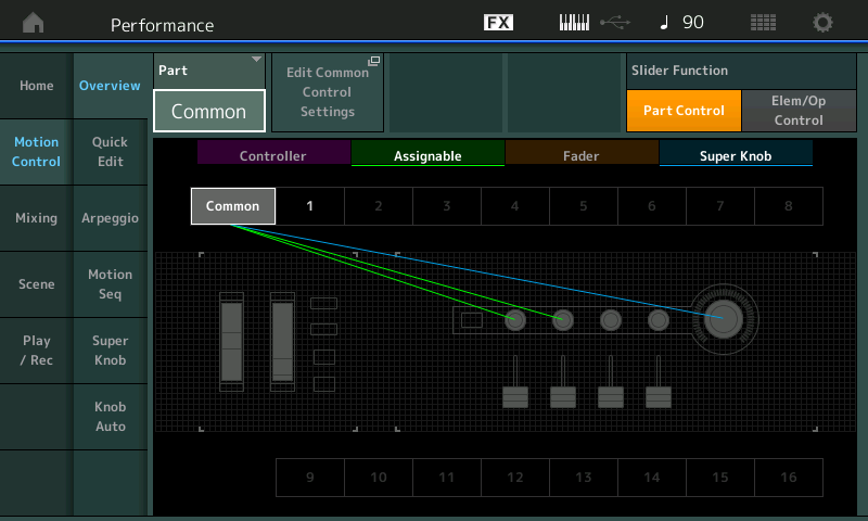
Here you can select to view Controller (Wheels/Ribbon), Assignable (Knobs/Buttons), Fader, and Super Knob assignment. Touch those words directly in the screen to toggle its connectors on and off. Shown are the “Assignable” Knobs (green) and the “Super Knob” (blue). Turned off in the viewer are the “Controller” and “Fader”. You can see how the two knobs and the Super Knob are linked to COMMON. Next, we will learn what this is representing.
TIP: In the “Part” box the word “COMMON” appears, change this using the [INC/YES] button or the DATA DIAL. You can select any of the numbered Parts 1-16 to update the graphic
- Return the item to “COMMON” on the OVERVIEW screen.
The box next to the PART = “COMMON” is a direct shortcut to the Controller Setting screen of the currently selected Part: “EDIT COMMON CONTROL SETTINGS”.
Touch “Edit Common Control Settings” to drop directly to the “Edit – Common/Audio” > “Control” > “Control Assign” screen.
This “shortcut” from the Overview jumps you directly to the controlled parameter setup.
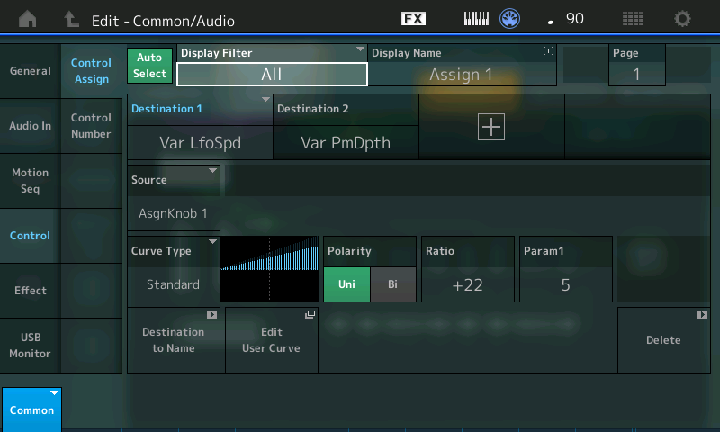
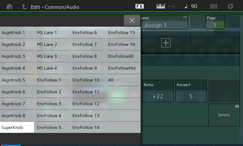
POWER TIP: Once you arrive on the Control Assign screen, you can view the 16 assignable Source/Destination functions to any ‘Part’ or to the ‘Common/Audio’ level. Four are shown at a time, by highlighting the “DISPLAY FILTER” box and selecting to view “ALL”. (Shown below):
If the [AUTO SELECT] is green, you can move a controller to see what is assigned to it or you can move the cursor to the “DISPLAY FILTER” box and use the Data Dial to view the available options. This Display Filter allows you to *view* assignments made to a specific controller – this must be stated less you believe you are making an assignment – when you change the “Display Filter” you are only changing what you are viewing on this screen.
Take your time with this screen because it is the key to the Matrix!
Above we are set to view “ALL” assignments – this is because the “Display Filter” is set to “All”.
We are currently viewing “Destination 1” (blue denotes current).
The “Source” controller is Common Assign Knob 1.
Curve Type = Standard
Polarity = Uni
Ratio = +22
Param1 = 5
Move the Super Knob to change the “Display Filter” to read what is assigned to its movement.
As we know both parameters are set to be moved by the Super Knob.
It is a Display *Filter* because it is allowing you to see just what is assigned:
- Assign Knobs 1-8
- Super Knob
- Motion Sequence Lanes 1-4
- Envelope Follower Parts 1-16, the AD, the Master
Or view “All”
Touch the “Display Filter” box to view the options (shown below):
The “Destination 1” box is assigned to control the “Var LfoSpd”. A box with a “+” sign will allow you to ADD a control routing (called a Destination). The “DELETE” box in the lower right corner will allow you to undo a Destination. There can be 16 Destinations (assignments) per PART. Destination 2 in our example assigns Assignable Knob 2 to Var PmDpth.
In future articles – where we tackle programming from the bottom up, you will see how by highlighting a parameter that you wish to control, the [CONTROL ASSIGN] button (left of the screen) will glow to indicate this is an assignable Destination parameter. Pressing the [CONTROL ASSIGN] button will make that assignment – it is that easy.
Common Assignments
At this upper COMMON/Audio level of the architecture this includes the following PARAMETER DESTINATIONS:
When you touch a parameter DESTINATION box the following option pop-in menu appears:
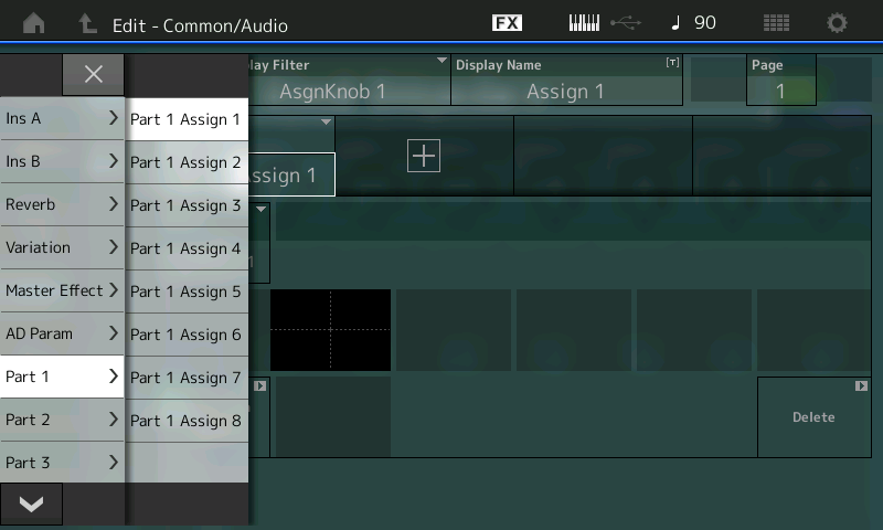
- INSERT A (when assigned to the A/D INPUT you can assign real time controllers to parameters of this Effect)
- INSERT B (when assigned to the A/D INPUT you can assign real time controllers to parameters of this Effect)
- REVERB (System Effect)
- VARIATION (System Effect)
- AD INPUT Parameters
- MASTER EFFECT
PART ASSIGN KNOBs
- PART 1 – Part 1 AS1 through AS8
- PART 2 – Part 2 AS1 through AS8
- PART 3 – Part 3 AS1 through AS8
- PART 4 – Part 4 AS1 through AS8
- PART 5 – Part 5 AS1 through AS8
- PART 6 – Part 6 AS1 through AS8
- PART 7 – Part 7 AS1 through AS8
- PART 8 – Part 8 AS1 through AS8
- PART 9 – Part 9 AS1 through AS8
- PART 10 – Part 10 AS1 through AS8
- PART 11 – Part 11 AS1 through AS8
- PART 12 – Part 12 AS1 through AS8
- PART 13 – Part 13 AS1 through AS8
- PART 14 – Part 14 AS1 through AS8
- PART 15 – Part 15 AS1 through AS8
- PART 16 – Part 16 AS1 through AS8
In our next example, we will see how this intermediate step opens the door to a wide, wide world of synth patching. We will drop down a level to the individual Part and to parameters that will only affect that single Part within the Performance. We will assign PART 1’s Assignable Knob 1 so that it follows the movement of Super Knob and yet controls a parameter exclusively (locally) within just one Part, PART 1. The selection of potential Destinations will change and will include parameters specific to this particular PART as an individual component within the PERFORMANCE.
Example programs used in this series of articles can be downloaded: SuperKnobExamples.X8U
If you have any questions or comments about this article, please join us to discuss them on the Forum here.
Next Article: “Mastering MODX: Super Knob Unipolar” is available here.