

Tagged Under
Manny’s FM-Xpert is a deep dive into the the FM-X engines of the MONTAGE and MODX Music Synthesizers. This five article series is delivered in an accessible and entertaining way and includes MONTAGE content programmed by Manny himself. The other articles in the series are accessible via the links below:
Manny FM-Xpert 1: “Acoustic Eccentricities and Stuff”
Manny FM-Xpert 2: “I’m Fixing a Hole Where the Timbre is Thin”
Manny FM-Xpert 4: “The Envelopes, Please”
Manny FM-Xpert 5: “Everybody’s Doin’ the Knob-O-Motion”
It’s Just a Phase, Man
Download the updated file associated with this article series here! (Manny FMXpert.X7L)
Previously in Article 2 of this series I mentioned the interaction of “Phase” in two contexts. One was the use of the Phaser Effect as a generalized Part tonal shaper, using the Manual setting of the effect delay (aka phase shift) parameter to make quick changes to the timbre avoiding the FM parameters. The second was in the context of how changes in FM Modulation Index change both the intensity of harmonics created in our sound and their phase. It is this behavior of FM synthesis that gives it much of its characteristic ‘flavor’ and gives both great versatility and great challenges in creating certain types of harmonic behaviors.
I covered this from a different perspective in the previous article in the series, mixing Operator stacks from different Parts or add in the missing harmonic pieces in our timbre. This article will discuss in detail the ‘how and why’ the ‘holes’ occur and show a technique to create fine, detailed control of this ‘natural’ FM behavior in the construction our FM-X Piano sound. Understanding that the amplitude and phase of the overtones (harmonics) has huge implications to our perception of timbre & sound, it’s important to be able to tweak phase for timbral shaping when needed. Advanced apologies — this gets pretty geeky in the first half so be sure to watch the companion video at the bottom of the article!
OK, let’s board our deep dive submersible and head on down for an overview of the harmonic behaviors underlying in FM synthesis, using the example of a classic sawtooth wave. The harmonic series of a classic sawtooth wave is every harmonic “n” has an amplitude of 1/n relative to the fundamental. Meaning if you were to build a sawtooth wave from scratch with additive synthesis to match it as it is generated from an analog oscillator or a digital (wavetable) oscillator, you would do it as follows — The fundamental (harmonic 1) would have an amplitude of 1; the 2nd harmonic at half (½) the amplitude of the fundamental; the 3rd harmonic at a third of the amplitude of the fundamental; the 4th at ¼ the amplitude, etc ad infinitum. The bare waveform is very bright and buzzy, and then in subtractive synthesis we apply a filter, typically a low pass with a -12db or -24db per octave slope, to attenuate the harmonics above the cutoff frequency. Harmonics below the cutoff frequency are not affected regardless of how much you continue to raise the filter cutoff. Velocity and envelopes are used to create the time and dynamic timbral behavior of the cutoff. The critical point is that the amplitude and phase of the harmonics are fixed and static in the base waveform, and application of the filter is uniformly applied to all the harmonics (based on the cutoff and filter slope). Dynamic changes of the filter cutoff setting have no effect on the loudness of the harmonics below the cutoff as you raise the cutoff frequency to allow more of the higher harmonics to be heard.
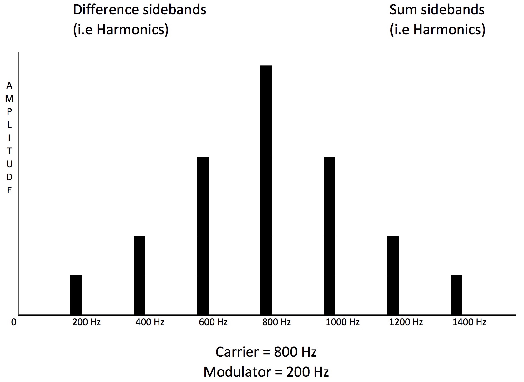
FM is completely different. To review some FM math fundamentals — when you modulate the frequency of a Carrier wave by and audio rate Modulator, you create sidebands (i.e. harmonics) that are a series of the sum and difference frequencies of the Modulator frequency added to/subtracted from the Carrier Frequency “n” times. Meaning, if you for example modulate a 800 hz sine wave Carrier with a 200 Hz sine wave Modulator, you will create the sum sideband harmonics at 1000 Hz (800 + 200×1), 1200 Hz (800 + 200×2), 1400 Hz (800 + 200×3) etc. The difference harmonics are 600 Hz (800 – 200×1), 400 hz (800 – 200×2), 200 Hz (800 – 200×3) etc. How many “n” harmonics are generated is dependent of the Modulator level, or Index:
Unlike tradition analog oscillators or digital wavetable waveforms, the amplitude of the harmonics in an FM created waveform are not fixed in amplitude, but are related to the Modulator Level (Index), and will both be increasing and decreasing in amplitude as the Modulator Level increases. This behavior of the amplitude of the Harmonics is determined by Bessel Functions, which look like this:
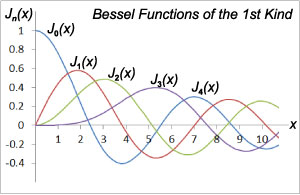
J0 (blue) shows the amplitude behavior of the fundamental, J1 (red) is the 1st (n=1) Harmonic; J2 (green) is the 2nd (n=2) Harmonic; J3 (purple) is the 3rd (n=3) Harmonic etc. The 1-10 on the bottom axis is the Modulation Index. Illustrates how the amplitude of the fundamental and all harmonics goes up and down in amplitude as the Index increases, and at certain points the amplitude is negative (phase inverted).
A curious question arises as to what happens when “n” gets large enough that the difference harmonics “pass through zero” and become negative. The short, broad answer is in Yamaha’s FM implementation the negative harmonics “bounce off” off zero back, phase shifted, into the ‘normal’ frequency range like light reflecting in a mirror or ripples in a pond bouncing off the shore. These two behaviors – sinusoidal evolution of harmonic amplitude with Index and phase inversion – is what gives FM it’s characteristic sound.
Back to our sawtooth wave example. We start to build a “sawtooth type” wave by setting a Modulator/Carrier Ratio of 1.00 to 1.00 This gives the harmonic template able to create all the possible “nth” harmonics just as in our sawtooth wave. To begin to hear those harmonics we increase the Modulator Output Level (the FM index). Now the key difference again as noted above – increasing the Modulator Level will brighten the timbre by creating more harmonics in the sound, similar to how opening the filter cutoff lets more of the harmonics through. However the amplitude of the harmonics created in ‘through zero” FM follow that non-linear mathematical behavior (Bessel Functions) and do not keep the fixed 1/n amplitude relation to the fundamental of a sawtooth wave as Modulation Index increases.
Great, so what does that mean soundwise to your ears or apply to Modulator Level settings? Here’s an example, detailed in the video below (please watch it!) to demonstrate the concept. Say we have an FM waveform with the Modulator / Carrier ratios both set to 1.00, and the Modulator Level set to 65. This creates a timbre very similar to a sawtooth wave with the filter closed down about ¾ of the way. The 2nd harmonic is about half (50%) the amplitude of the fundamental; the 3rd is about one third (33%), the 4th is about one forth (25%), and the 5th and higher attenuated so they’re about half of the natural 1/n amplitudes (10% – 5%). Now to mimic the ‘opening of the filter cutoff’ in the classic sawtooth wave / subtractive synthesis example, we need to increase the Modulator Level (Index). If we increase the Modulator Level to 78, the 2 harmonic will increase to an amplitude of 75% of the fundamental, the 3rd to 60%, the 4th to 50%, the 5th to 40%, the 6th to 30%, the 7th to 25%, etc, and the fundamental will actually decrease to half the original level! So the sound starts to sound less than the original sawtooth as the amplitudes are completely different. Continuing to increase the Modulator Level to get a lot of brightness from increasing the high harmonics above the 16th will then also start to decrease the amplitude of the 3rd, 4th and 5th harmonics. This is because of Bessel Function behavior means the harmonic amplitudes change non-linearly with the FM Index (i.e. Modulator Level). Increasing the Modulator Level to 86 changes the relative levels of all the harmonics once again, and the fundamental gains amplitude, creating a sound very similar to a filtered pulse wave. And at these higher Modulator Level settings, the Bessel Function behavior becomes much more pronounced so even changing the Modulator Level just 4 increments from 86 to 90 makes drastic changes in the timbre due to the non-linear evolution of the harmonic amplitudes and the phase inversions. Again, please watch the video at the bottom of the article!
Algorithms and Maths and Phase: Same as it ever was…
As you hear this happening with just a simple 2 Op Stack, you can imagine what happens with 2, 3 and 4 Op stacked and/or branched Algorithms, where we have Modulator Ratios of 1.00, 4.00, 5.00, 7.00 and higher. There’s no ‘linearity’ to the timbre as the Modulator Levels change, so how do we make our sound play with the essentially linear dynamic timbre response of a Piano? Well, you will remember from the prior articles I made liberal use of the Montage Filters to create the dynamic brightness, and smaller amounts of Velocity Sensitivity for the Modulator operators. In addition, using the harmonic component modeling concept I utilized multiple 2 operator stacks in multiple Parts to independently create specific portions of the overall harmonic spectra. These were combined back in an ‘additive’ manner to the final timbre, controlling their intensity directly by their Carrier operator velocity settings. This was one way to separate the addition of more harmonics from much of the weird FM math behaviors, phase inversion and ‘holes’ that would have occurred if we attempted to add those harmonics using more Modulator Level, or additional Modulators within a more complex stacked/branched Algorithm.
Now knowing that due to the math quirks of FM the phase of various harmonics can interact and compromise our desired timbre, lets consider the converse scenario – can we use phase interactions to improve our timbre in a desired, controlled way? In other words can we use this phenomenon as another method to ‘fix the holes’ in our timbre, or better yet, change just certain harmonics and avoiding the otherwise wholesale changes in the harmonics created by the natural FM behavior of changing Modulator Level? Yes we can, and ideally this could be simply done by having a phase parameter setting for every Operator as in AFM synthesis on the Yamaha SY77/99. In those synths, precise tweaks of Operator Phase for specific Modulators in complex branched/stacked algorithms can prevent the ‘hole’ from occurring, or shape the timbre without changing Index or Ratios. FYI – to hear an example how this can be used to model the behavior of a analog filter, check out this Soundcloud example on the SY99. While FM-X does not have an Operator phase parameter, there’s a trick and a backdoor to get similar results.
Again, it’s important you watch the video at the end of this article to hear the following examples in action. I’ll start with the trick (covered briefly in the prior article “Fixing the Holes…”), which is a focused use of a Part’s effect processing – the Phaser effect specifically – as initially mentioned in the prior article. From the Live Set select the Performance “MF.HCM WrmSus7fSH2” and exit the Live Set. Compared to the “close mic’ed’” type timbre of Pianos Ex1, 2, 3 and 4SH in the Live Set, this Performance is meant to capture the warmer timbre of hearing a piano in a natural room setting. Go into Performance Edit mode and select Edit\Common\Audio and turn off the Master Reverb. Then select Scene 3 to isolate Parts 4, 5, & 6. All three of these Parts are used in this performance emphasize ‘warmth’ in this sound, which is quite different in timbre than Pianos Ex1, 2, & 3. And a large part of then ‘warmth’ comes from using the Phaser effect to enhance the 2nd and 3rd harmonics. To hear how much the Phaser effect is enhancing the timbre, go to Edit\Part\Common\Effect and turn off the Phaser insert effect for each of these Parts and play the sound – you will hear the Phaser is clearly enhancing the low order overtones to fill in the holes in the basic timbre from Part 1. (BTW- this can also be done with a different flavor using the Flanger effect)
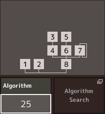
So, with the right Phaser settings this trick can be very effective but somewhat limited as it doesn’t allow for control of phase at the Operator level, as it is applied to the entire Part. For individual Operator control of phase we need a backdoor, and fortunately we have one – in FM-X each Operator has it’s own Pitch EG ! To show this in action, lets again select the Performance “MF.HCM PianoEX1.” We’re going into Edit Mode, Select Part 2, which is the first “thickening” Part for the lower register for our HCM Piano. Mute Parts 1, & 3 through 8 – we want to look at Ops 3 and 4 for Part 2. They are a “branch” in the Ops 3-8 stack:
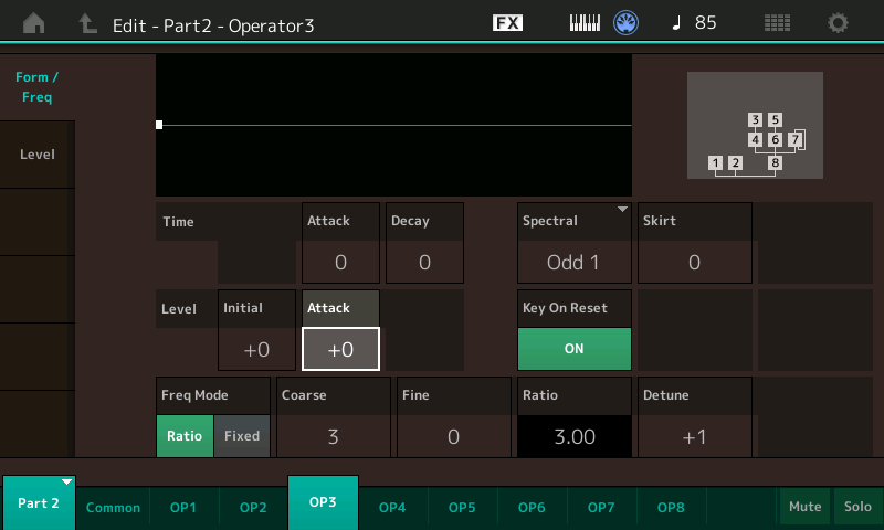
Below are the Form and Frequency Settings for Op 3:
Here are the Form And Frequency Settings for Op 4:
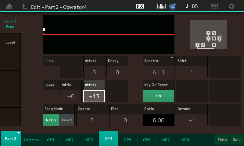
Now you will notice Op 4 has the Pitch EG Attack level set to +13. Next, play G2 (G below middle C) repeatedly as you simultaneously use the Data Wheel or the Dec/No button to gradually change the Attack value from +13 down to zero and hear how the timbre changes. Note especially how different it is with values of +13 and +6. So, what’s happening here as the timbre changed without us changing the Operator Frequency Ratios or the Modulator Level (Index)?
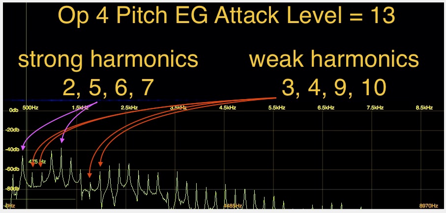
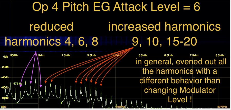
What has occurred is the quick, positive (sharp) Pitch EG Modulation of Op 4 changed it’s phase relative to all the other Operators, which through all the quirky FM math results in changes in the amplitudes of the harmonics in the final waveform. Very simply, the Phase shift of Op 4 caused of ‘cancellation’ or ‘reinforcing’ of certain harmonics, making some softer and others louder — very similar to what the Phaser Insert Effect did for the whole Part. But the Pitch EG backdoor allows for fine tonal shaping at the Modulator level within the Part ! Just for fun, select Op 3, and start changing it’s Pitch EG attack level, and hear a different flavor of the same effect. The specific harmonics altered by this Pitch EG trick are influenced by the Operator Ratio Tuning, the Spectral Waveform and the actual Pitch EG settings. If you look through all 64 operators in all 8 Parts of our sound, you will see I’ve tweaked this for 45 of them and in some other Performances in the Library — nearly all of them! Again please watch the companion video below as this is easier to grasp if you see & hear than just reading:
So to shape the timbre in a particular way, you may ask yourself how do I work this… ? And you may ask yourself where does that highway lead to… ? (Apologies to the Talking Heads…)
Basically, how would one even figure out where to begin editing like this…? I would answer “Start with the Modulator with the highest Output Level, having the Ratio setting creating the harmonic range you need to tweak, that’s in the Part that contributes the greatest amount of that harmonic range in the final sound.” That may sound like a bit of a vague answer, but that’s what I personally found most efficient after the extensive hours creating & tweaking the progression of Piano sounds that culminated in the 16 Performances included in the Live Set! … Gave me flashbacks to programming the VL1 Physical Modeling engine where we developed a generalized editing approach – an algorithm so to speak, no pun intended – to nudge values in particular groups of the model parameters to get us the results we needed. Hence, “Harmonic Component Modeling” is a very apt description of what’s going on, and in FM-X it is much more sophisticated than in the TX816 as there was no way to accomplish this level of detailed harmonic tweaking.
Hopefully you’re head isn’t spinning right ‘round like a record, baby! To settle things down in your noggin’ a little before we move on to the next article, please take some time to play & listen to Performances “MF.HCM WrnSus7fSH2”, “MF.HCM2WrmSusUD4eOP7”, “MF.HCMBrtSus7i3” and “MF.HCMOld Soft Felt”. These “warm room” Performances have expanded utilization of the topics discussed here, along with different allocations of the Ops/Algorithms across the Parts, to create a completely different range of timbres compared to the “Piano EX” performances. Now that we’ve created our timbre and harmonic structures in detail, we have to control them and make them playable. So, next up, “The Envelope(s), Please.” If this article got way too deep into the depths of arcane FM concepts, rest assured that our next topic will be much more relatable!
Check out the previous articles in the series:
Manny’s FM-Xpert #1: Acoustic Eccentricities and Stuff
Manny’s FM-Xpert #2: “I’m Fixing a Hole Where the Timbre is Thin”
Next up, “The Envelope(s), Please.”