

In an effort to show how to go about building basic wave shapes using FM-X parameters, we’ve looked at four different, simple 2-Operator FM-X Single Part Performances – each using just a simple Modulator:Carrier stack. Now lets move on with a look at a Multi-Part Performance. Please find the zipped download example at the end of this article.
This is an edited version of the Factory Preset: Moving Floor
Exploring FM-X “Moving Floor(ex)”
Please download this edited version at the very bottom of this article – it is provided in a “MONTAGE Connect” Bulk file, .X7B. It’s been edited so that the different AssignKnob functions have been identified per Part and for the Super Knob’s AssignKnobs. This program is made up our four very simple FM-X components, and as we’ve seen in our previous installments, by looking at each of the FM-X component individually, it leaves plenty of room to build. The “Motion” here is provided by the Arpeggiators; and “Motion Control” is involved in the selected Part parameters that are linked to the Super Knob.
The FM-X Parts 1, 2, 3 and 4 are those that we have studied over the past few weeks, so they should sound familiar and their behavior will be familiar now. While many people think you need 8 Operators to create intense complex tones, we’ve seen that it all begins with just a simple two Operator stack; the basic M:C (modulator:carrier) interaction, and we’ve learned that because each Operator can begin as a more complex Wave than the traditional (FM) Sine Wave, you can vary the timbre, shaping the harmonic content in ever more interesting ways. In keeping with our learning to swim analogy: we have waded out with our snorkel gear, and peeked under the surface at some very basic relationships. In future articles, here on YamahaSynth, we will get out the Scuba gear and go even deeper. The key thing to take away from this is: *exploring* is one of the best ways to learn. We have revealed some of the basic fundamentals of FM synthesis. We’ve done so avoiding the heavy math (we never even mentioned Bessel functions once) to show that you can accomplish a lot without it. Don’t over think or over analyze, use your ears first – then seek out the reason why it behaves as it does.
Keep in mind the Modulator (like the vibrato added by the violinist’s left hand) is not audible by itself; its influence is manifest as a change in the Carrier (the violin string in motion). It is the Carrier that is audible. It is the Modulator that affects the tone.
The “Recipe”
This Performance is made up of the four FM-X Parts, 1-4, plus a single Element AWM2 pad (Part 5 “Dance Pad”) and a Drum Kit (Part 6 “Dancefloor Kit). You can mute this rhythmic Part or replace it with any percussion of your choosing. If you’ve experimented with Blake’s “MONTAGE Connect Arpeggio 101” experiment, you can use the Drum Arp you created for that tutorial. Mostly we will be concentrating on the AssignKnobs and their interaction with each of the Parts we’ve studied.
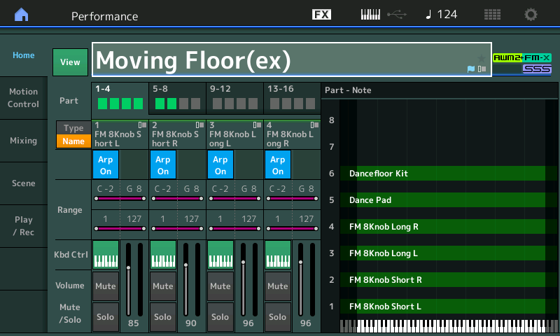
Play through this Performance while on the basic [PERFORMANCE (HOME)] screen, shown below, where you can view all Parts and their metered activity. Move through the eight Scenes (blue buttons). You will see that not all Parts are in each Scene, and the Super Knob causes sonic changes in the tone.
A SCENE can, among other things, remember what ARP SELECT 1-8 is playing. And while SCENE memories can also remember MUTE status – we are not using that here. When a PART is not active via an ARPEGGIO it is because it has been instructed to “rest”. More on that in moment, as well. Even if this type of “One Finger Performance” is not your cup of tea, the ARPs here make it very easy for us to explore and learn about what is happening in the FM-X engine. Because the ARP is “playing” the phrases, we can concentrate our attention on designing the sound – which is fun!
Let’s explore PART 5:
- Press [PART SELECT 5];
- Press [EDIT];
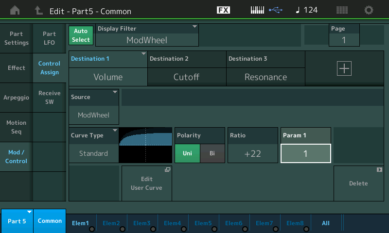
- Touch “Mod/Control” > “Control Assign”; and,
- With the AUTO SELECT box active (green) move the MOD WHEEL to recall the screenshot shown below.
The MW is actually responsible for Volume, Cutoff, and Resonance. [SOLO] PART 5 and move the MW to hear this:
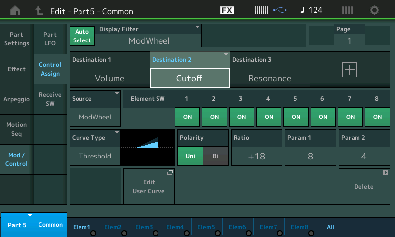
The assignment of both FILTER “Cutoff” and “Resonance” to the same SOURCE (controller) allows a single gesture to simultaneously open the Filter (raise the Cutoff frequency) and decrease the Resonance so that the sound doesn’t “run away” and go crazy, howling at the moon (remember “resonance” is that spike at one particular frequency making it louder than all others that can send harmonics flying off into the stratosphere); all this while increasing the volume of the PART. You can hear this by holding a chord as you slowly raise the MW. Hear how it is not just a linear sweep, it is multi-dimensional. You can see in the graphic above (Curve Type) how Cutoff is increasing as the MW is advanced. It begins to increase at about 1/3 of the way. But there is more going on….
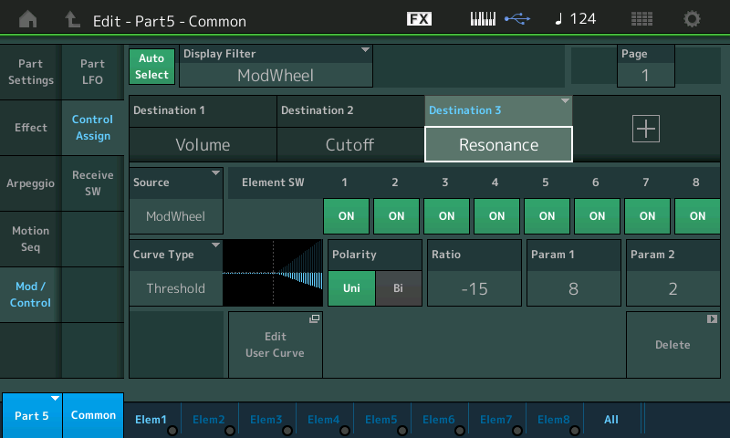
Part 5 is single Element AWM2 PART – in keeping with the very minimalist construction. In the graphic below, we’ve highlighted the Resonance Control Box (Destination 3) to show how Resonance changes when the MW is advanced. At about half way, the Resonance is reduced:
The MW is responsible for moving three parameters simultaneously. When you highlight the VOLUME parameter (Destination 1, shown below) you will see that it immediately increases as the wheel is moved – the “Param 1” weights this Curve so that the change in volume occurs early in the movement of the MW… while the movement of the Cutoff Frequency and Resonance is delayed a bit. This, as we’ve seen is how the Control Box for each assignment allows you to shape the application of change. It does not have to be a linear movement, it can be customized to a dizzying degree, and shaped as you desire:
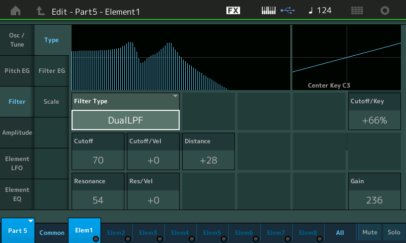
- Touch “Elem1” along the bottom of the screen or press the first button in row 3 on the right front panel (Element Select 1) while in PART EDIT.
- Touch “Filter” > “Type”:
Extra Credit: Move MOD WHEEL parameters with FC1
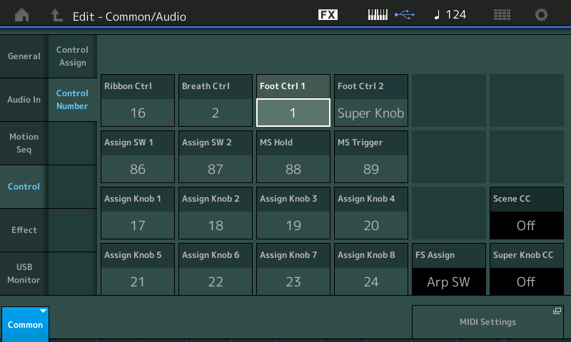
For those of you with two FC7 pedals, you can opt to assign FC1 to become your Mod Wheel – allowing you to control this movement with your foot while keeping both hands on the keys.
This is done by navigating to the “COMMON/Audio” > “Control” > “Control Number” screen and setting Foot Ctrl 1 = 1:
The “Buttons Map”
Performance Control – allows you to ‘work’ the front panel while performing. This is a synthesizer, so you expect that working with the front panel is a part of performing.
A close look at the front panel reveals that the [Performance Control] button is connected by a dotted line to the words “PART SELECT” (row 1). Selecting a PART means its Knob Assignments will appear on the screen and the twenty-four TONE, EQ/FX, and ARP/MS Knobs apply to just this one selected PART:
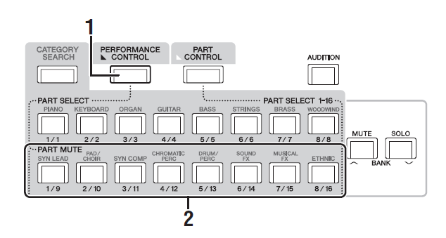 The second row of buttons, “PART MUTE” can [MUTE] or [SOLO] the corresponding Part directly, 1-8. Get comfortable Muting and unMuting Parts. This will be an essential skill in focusing our listening attention on specific components.[SOLO] let’s you listen to just the ONE selected Part, while manipulating several of the the MUTE buttons you can chose to listen to any combination of Parts. Therefore, to listen to multiple Parts in combination, you would use the [MUTE] function.
Once you’ve selected a Part – its [PART SELECT] LED will be lit – you have, in effect, entered that Part and you’ve “opened” it for exploration. You will notice that the FADERS now become OUTPUT LEVEL for the ELEMENT (if AWM2) or OPERATOR (if FM-X) of the currently Selected PART.
If you then press [EDIT] – you enter Edit mode on the Selected PART – you can then Mute and unMute the individual Operators or Elements (within this Part) using the bottom (4th) row of buttons. The 3rd row (directly above) lets you Select the different Operators/Elements. Again your [MUTE] and [SOLO] buttons for the Operators or Elements are to your lower right.
_ If AWM2 is involved you will be able to hear when that Element is active if it meets the required parameters as outline within the PART (key range, velocity range, etc).
For this experiment set the MW at minimum (Heel down if using FC1 as MW). If you do so, you will hear just the following PARTs as stored in the Scenes: While holding a Chord or note on the keyboard advance through the 8 SCENES (blue buttons) allowing each to play for several measures:
- Scene 1: Part 4, 6
- Scene 2: Parts 3, 4, 6
- Scene 3: Parts 3, 4, 6
- Scene 4: Parts 2, 3, 4, 6
- Scene 5: Parts 1, 2, 3, 6
- Scene 6: Parts 1, 2
- Scene 7: Parts 1, 2, 3, 4, 6
- Scene 8: Parts 3, 4, 6
And again, you can bring in PART 5 at any time by advancing the MW (or FC1).
ARPEGGIO NAVIGATION:
Let’s take a look at the ARPEGGIO ASSIGNMENTS. We want to call to your attention two different views of the ARPEGGIO data.
In the first view, shown below, you are seeing an overview of all the active PARTS (you can view either 1-8 or 9-16) and the assignment of the ARPEGGIO Phrases for each of the 8 ARP SELECT locations. This view is helpful, when multiple PARTS are following arps. You are viewing what is happening right now for the currently Selected Arp, 1-8 : ARP SELECT #1 is active in the screenshot:
- Press [PERFORMANCE (HOME)].
- Touch “Motion Control” > “Arpeggio”:
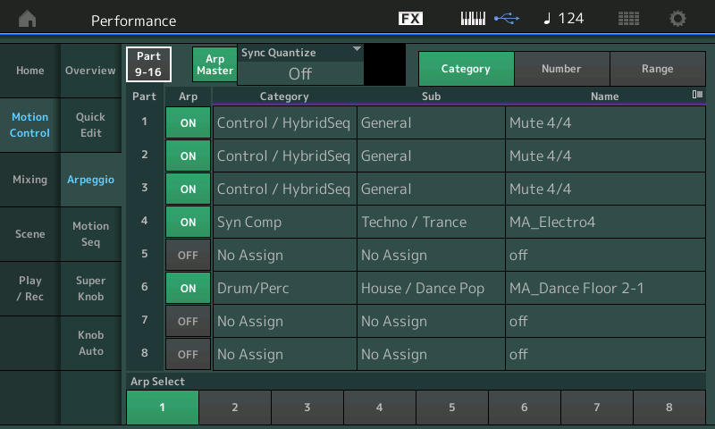
Here you are looking at PARTs 1-8. You see that PARTS 1, 2, 3, 4 and 6 will at some point, be responding to an arpeggio phrase. Currently ARP SELECT 1 is active (bottom of the screen). Notice that PARTs 1, 2 and 3 are assigned to play an ARP named “Mute 4/4” — this is equivalent to placing a musical REST in this location. It allows the PART to stay ‘armed’ and in synchronization with the clock – it will just be silent – like a musician reading rests on a page – they don’t play, they simply count the time. This is quite different from “OFF”. And that is the takeaway here. “OFF” means you would have to re-arm and then re-trigger a key to restart the PART arpeggiating. If you use a MUTE ARP phrase Type, then the PART will simply come in automatically at the top of the next measure, if an arp phrase is posted in the next SCENE. This screen view shows us what each of the PARTs is doing for ARP SELECT 1. The MUTE Type arpeggio phrase is used instead of the regular PART MUTE button.
Notice: Arps are set to change at the “top” of the next measure. When you press a SELECT button to change SCENEs, the phrase does not change immediately – you can choose to have the ARP wait until the top of the next measure.
But what if we want to view just the ARP Phrases assigned to the PART 4, individually, for example. There is a Part view of the Arpeggio assignment:
- Press [PART SELECT 4];
- Press [EDIT];
- Press the lower [COMMON] button or make sure “COMMON’ is active in the lower left of the screen; and,
- Touch “Arpeggio” > “Individual”:
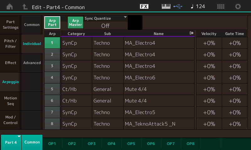
Here you are looking at the PART 4 Arp Phrase assignment across the eight ARP SELECTIONs.
For now, recognize these two different views. As they will come in handy when you are making and assigning your own Arpeggio Phrases. The take away here is that for convenience you have these two views. The overall view (all Parts) and the individual Part view. Each PART will have its own set of assigned phrases.
PART 4 is active
For this experiment, select SCENE 1. Press [PART SELECT 4]
Doing so will show you the PART 4 Assign Knobs in the screen:
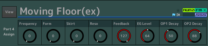
As you move the SUPER KNOB (or advance the FC7 pedal assigned to Super Knob), you will observe that Part 4’s AssignKnobs 1, 6 and 7 are linked to its movement. PART 4’s AsgnKnob 1 moves the distance 0~127, PART 4’s AsgnKnob 6 moves from its stored value 64~127, while AsgnKnob7 advances from its stored value 50~127:
- AsgnKnob 1 is doing “Operator Frequency” (Modulator).
- AsgnKnob 6 is changing “EG Level” (Modulator).
- AsgnKnob 7 is changing “OP1 Decay” (Modulator).
You should recognize this as “P4” in our FM-X Explorations article: the range settings for each of the PARTS is being determined by the Motion Control > Super Knob VALUE 1 and 2 settings. These determine just how much change is applied. The assignments to the Super Knob’s Assign Knobs, takes place here:
- Press [EDIT]
- Press [COMMON]
- Touch “Control”
- Touch “Control Assign” (there are 8 Assignment Destinations in this Performance, four are shown per PAGE, tap “PAGE” and advance to PAGE 2.)
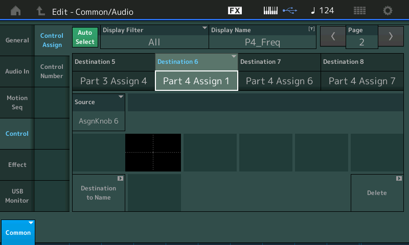
If you highlight “Part 4 Assign 6” you will see it is linked to the Super Knob’s AsgnKnob7 as its SOURCE.
And if you highlight “Part 4 Assign 7” you will see it is linked to the Super Knob’s AsgnKnob8 as its SOURCE.
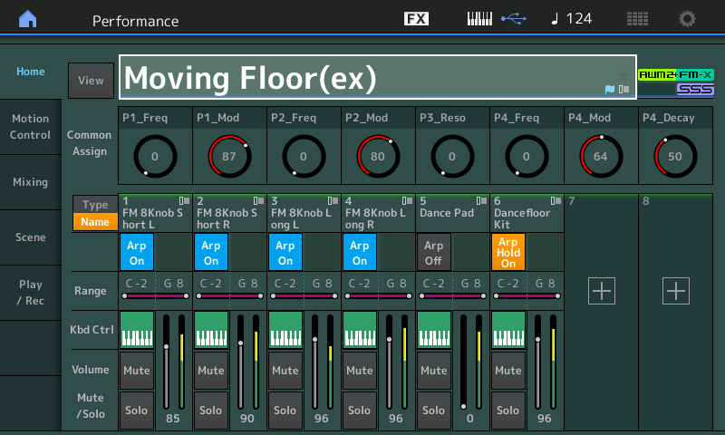
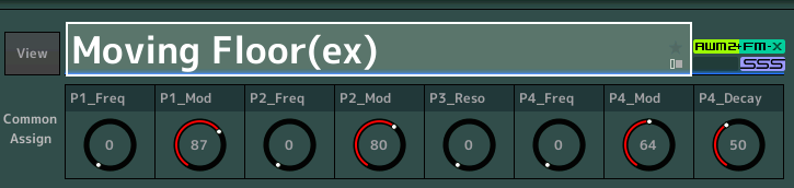
From this we now know that on the Super Knob level of editing: Knobs 6, 7 and 8 will move 0-127, 64-127 and 50-127, respectively. If you now press the upper [COMMON] button, you will see the COMMON ASSIGN knobs in the screen. And you can see that Knobs 6, 7 and 8 are being applied to PART 4. The Display Name appears for KNOBS: Knob 6 (“P4_Freq”), Knob 7 (“P4_Mod”), and Knob 8 (“P4_Decay”). You can directly move these Knobs to affect change on PART 4. Try it:
PARTs 3 and 4 are active, along with the Drums.
SOLO PART 3 and SELECT it. View PART 3 Assign Knobs in the screen. As you move the SUPER KNOB, you will observe that only Part 3’s Assign Knob 4 (Resonance) is linked to the movement. You will recognize this as “P3” from our second article in this series.
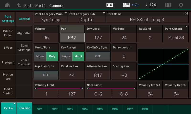
Press the [MUTE] button and use the second row of right front panel (PART MUTE) buttons to isolate just PART’s 3 and 4.You can hear how PART 3 is mostly in your left speaker with some content that sneaks over to the right channel, and PART 4 is mostly in your right speaker with some content that sneaks over to the left channel. This is accomplished though PART Pan parameters (Part 3 is panned “L32”; Part 4 is panned “R32”). The bits that sneak over to the opposite channel do so because the “Alternate Pan” and “Random Pan” parameters on the PART ‘x’ > “Part Settings” > “General” screen – shown below for PART 3 and PART 4, respectively:

SCENE 3:
Same as SCENE 2 except the Drums have added a Snare sound layered with the Kick drum.
SCENE 4:
PARTs 2, 3 and 4 are active along with the Drums.
PART 2 has joined PARTs 3 and 4, bringing in a counter-rhythm. You should recognize this as “P2” from the previous article.
SOLO PART 2 by pressing the [SOLO] button, and then [PART SELECT 2]
Part 2 has two parameters linked to the Super Knobs: Operator Frequency (Knob 1: 0-127) and EG Level (Knob 6: 80-127)
When you return to the COMMON ASSIGN view, you can see the two linked parameters listed as “P2_Freq” (Common AssignKnob 3) and “P2_Mod” (Common AssignKnob 4) – giving you direct access when on the HOME screen.
SCENE 5:
PARTs 1, 2, 3 and 6 are active. PART 1, which is a bookend to PART 2, joins in and replaces PART 4. PART 1 is duplicating the arp phrase of PART 2. PART 1 (“P1”) has the same two parameters linked to the Super Knobs. Again, it is Operator Frequency and EG Level, but moving through a different range for “EG LEVEL”. “Operator Frequency” (Knob 1: 0-127) but “EG LEVEL” (Knob 6: 87-127) – creating a bit of dissonant ring.
When you return to the COMMON ASSIGN view, you can see the two linked parameter listed as “P1_Freq” (Common AssignKnob 1) and “P1_Mod” (Common AssignKnob 2) – giving you direct access when on the HOME screen.
SCENE 6:
PARTs 1 and 2 are active; all other arps are resting (MUTE 4/4). You can play chords with your right hand and fade in the Pad (PART 5) by slowly raising the MW.
SCENE 7:
PARTs 1 and 2 continue with the same phrase, but are joined by all the others; 3, 4 and 6, slowly fade out the Pad (PART 5).
SCENE 8:
PARTs 3 and 4 continue, while PARTs 1 and 2 go to MUTE 4/4; a hihat joins the Kick drum in PART 6.
The individual Assign Knobs can be moved directly, whenever you desire. We have brought the Super Knob linked parameters and show their “DISPLAY NAME” so you have access to them. Because moving the Super Knob (at any time) will cause all those parameters linked to it to change together, while accessing a COMMON ASSIGN Knob directly gives you individual unique control.
Summary and Final Thoughts
How you go about editing and approaching any MONTAGE Performance is a personal thing. Hopefully some of the instructions here will tweak your imagination to go in directions of your own. Do not feel the need to over analyze everything. We picked out a few things that make a point about how things are designed to work. It becomes very easy to disappoint yourself when learning through this exploration and discovery method. When you first learn to drive a car, it is very easy to make the complaint that “how come the car can’t fly?” You get so used to getting from place to place faster than you could walk or ride your bicycle – but don’t jump to conclusions that it will take you to the moon. For its purpose, the car moving as it does, will suffice. That said, we probably never would have flown to the moon if someone hadn’t thought ‘wouldn’t it be cool if…’ but that is product design, not SOUND DESIGN. The purpose here was to learn to use the Crayons in this box, to create your picture – not to design a different product. (Although it’s fun to imagine the future…)
Once you begin to see the scope of what is happening here, such a request would require (perhaps) just a little too much CPU power. We have been looking at a PERFORMANCE that uses only a small portion of the processing power of the MONTAGE. We have left 48 Operators doing absolutely nothing. We have used an AWM2 (Pad) PART that leaves 7 of its Elements doing absolutely nothing. And from the Drum Kit with 73 Elements, we are using approximately a half dozen different sounds (kick, snare, hihat, etc). When you start to realize the size of the controller matrix you are actually dealing with, you begin to appreciate what is going on.
This Performance (Moving Floor) is a ‘snorkeler’s delight’, because of its simpicity. When there is actually a lot going on, you may begin to scratch your head about what is doing what to what. Please come back for future Exploration tutorials. It is important to experiment and to learn to navigate to the various areas of the MONTAGE architecture. Getting used to Performance Control and PART selection, and then Part parameter controls.
FM-X Final Notes: This particular Performance had a very unique selection of knob assigned parameters. Each FM-X sound is likely to be entirely different in layout and assignments. The idea is when finding a sound you enjoy playing, lose the fear, dive in and explore what is assigned to do what. We basically had one thing assigned per knob, with one or two exceptions. When going deeper you will discover that multiple items can easily be assigned to a single Controller each with customized results, there is no one-way to accomplish a goal.
Enjoy Mastering MONTAGE!
Need to catch up/revisit the earlier lessons? Find them here:
Want to discuss this article or series? Join the conversation on the Forum here.
And keep your eyes – and ears – open for more on mastering your MONTAGE soon!
Download here: Moving_Floor_ex.X7B