MONTAGE: Velocity Sensitivity

Tagged Under
Velocity Sensitivity
To see and hear how Velocity works we ask you to choose any Single Element PART from the Factory Set, for example: “Ens Mix“ (Strings) or “Acoustic Piano DA“ (Acoustic Piano). This will make it easier to learn – as you will not have to deal with extra components – one Element will let us focus our attention in on how this works.
From the Home screen:
- Press [CATEGORY SEARCH]
- Type in the name under the Magnifying Glass: “Ens Mix” > [ENTER]
Level/Velocity – Offset – Curve within the AWM2 Element architecture
From Home:
- Press [EDIT]
- Press [PART SELECT 1]
- Touch “Elem 1” in the screen to view Element 1 parameters
- Touch “Amplitude” > “Level/Pan”:
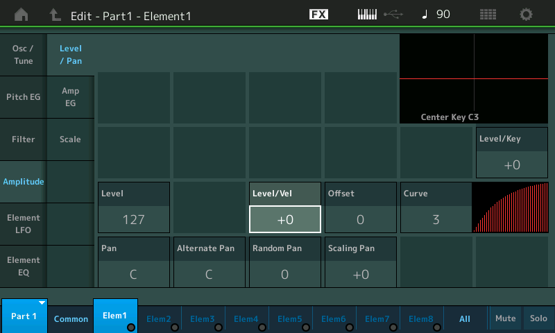
“Level/Velocity” is a sensitivity parameter responsible for interpreting the speed at which a key is depressed and turning that into an output result. It can be best understood as a DEPTH parameter, because it has to do with ‘how much’ is to be applied to get a desired result. It’s range can be set positive or negative. When “Level/Velocity” = +0, the Element will not respond to Velocity at all, but output will be fixed at the Element’s LEVEL setting (127).
First, lets talk about the “normal” (positive response) and then we can discuss the unusual. It is normal for a musical instrument to increase in volume as more effort is used to hammer, strike, pluck, blow or bow it. It is also true that as you increase that effort the richer the sound is in harmonics (high frequency content). Velocity Sensitivity can be directed toward each of the three major building blocks: OSCILLATOR, FILTER, AMPLIFIER to have an influence on pitch, timbre, and/or loudness.
The standard “linear” velocity curve (normal) would be for each increment of effort you increase the key-on velocity, 1-127, there will be a corresponding increase in the MIDI Output level, 1-127. Say you played something and the velocity you used or the velocity of the recorded MIDI data did not give you enough audio output. The Level Velocity Sensitivity Offset allows you to increase the output result (or if you lower it, decrease the output result).
Toggle through the CURVE parameter settings and understand each one – as to the degree of ease or difficulty you experience in increasing Output (volume, in this case) per velocity Input. Curve “2” is linear. For each unit increase in velocity there is a unit increase in volume output. Low velocities are soft, high velocities are loud:
Compare the playability of Curve 2 versus Curve 3. Understand that while linear may seem logically what you want (your eye would pick it), perhaps Curve 3 (the so called “soft” curve) is more appropriate for how you approach playing a particular sound. Try it on the Strings, try the same comparison on the Acoustic Piano sound. You will find that your preference for response may change depending on the instrument sound. And remember you have this same input/output, velocity/response control on a per AWM2 Element.
The graph in the screen would place a 0 value in the lower left corner of the box.
“Input” effort (Key-On velocity) is the x-axis: moving left to right.
“Output” result (Amplitude in the case) is the y-axis: moving bottom to top.
If you press a key with a velocity of 64, the Note generated would be at a volume of 64.
When the CURVE is set “3” (referred to as “soft”) understand the graphic as showing how easy it is to increase Output per Input effort. The graphic is not linear but rises initially with less effort.
If you press a key with an input velocity of 64, the output volume would be significantly higher than 64.
That is what these Curves do for you – the alter the INPUT effort versus OUTPUT results. This is all personal preference!
Suggestion:
To hear clearly:
Try CURVE 1 (Hard) understand how it takes more effort to make this Element loud now. The line in the graph travels farther on the Input axis before it rises along the Output axis – more effort to get loud:
CURVES 4 and 0, are hybrid curves that are initially difficult and then easy, and initially easy and then difficult, respectively. These are sometimes called the “wide” curves.
Again, you select these based on ‘feel’, personal preference, how you like them to respond.
When “Level/Velocity” = +32 on its scale from -64 thru +63, and you have set the “Curve” = 2, you have “true linear” response.
“True Linear” response is just a setting, it does not mean that it will feel right, this is what you are adjusting to your particular playing style, for *this* particular sound. You are playing on a set of piano-style keys, you are trying to make them ‘feel’ like you are playing, Strings, etc., (it’s sci-fi, it’s not real). There is no CORRECT way it should feel. How it feels to you, the response you get for input, will be your personal opinion and therefore CORRECT, for you! Make sense?
Experiment 1:
- Level = 127
- Level/Velocity = +32
- Offset = 0
- Curve = 2
As you change OFFSET, notice it gets easier to get Output from a key strike. Until at Offset = 127, it is impossible to be quiet at all. The softest key strike results in this Element reproducing full output.
If you do the same thing with CURVE set to the “3” (easy) setting, you’ll now notice that when Offset is increased from 0, by the time you reach an Offset of 64 you have already reached maximum output. Increasing effort beyond a velocity input of 64 has no increase in output level. It becomes extremely easy to reach full output.
If you now do the same experiment, change the Offset, but this time start with CURVE 1. Feel how the response is initially hard and as you increase the Offset value it is easier to reach maximum output.
Experiment 2:
- Level = 127
- Level/Velocity = +63
- Offset = 0
- Curve = 2
At this setting (“Level/Velocity” at the +63 maximum) notice this is far from being “linear” in response. In fact, only when you apply an Input of maximum effort do you get a note at all. For all low velocities the Element doesn’t output sound, only when Input is extreme does this setting allow any Output. This would be useful for setting velocity curves where an Element only arrives at particular playing velocities. Imagine another Element that would sound in response to increased input and then disappear at extremely high velocities. This would be one way to setup sonic crossfades between Element contributions with a Part.
Move the cursor to highlight OFFSET and vary it, as before, as you play the keyboard at various velocities. This time vary the Offset but your observations will be vastly different. The settings for Level Velocity Sensitivity (depth) and the Offset determine the real response curve for this Element.
All values above linear (+32) that is, an Level/Velocity sensitivity of +33 or greater, means that no output at all is produced from extremely low velocity inputs. And by the time you offset +63, only an extreme highly velocity input produces an output. The original Element setting for Level Velocity Sensitivity was +14. This is the value the original programmer felt delivered enough Output (result) for a low velocity strike. If you continue to strike a key with low velocity as you raise this parameter, you will notice the sound getting softer as the Sensitivity increases, it results in a wider response curve.
You can see now why I suggested you work with just a single Element set to full velocity range. It can get gloriously complex with multiple Elements!
As you increase the OFFSET value in this second experiment observe how low velocities behave, as you increase it 16… 32… 64… 96…
Summary:
Each Element has its own customizable response to Velocity. And this is the type of thing that makes for the incredible detail within the way sounds behave. We’ve been looking at the Amplifier (Amplitude Envelope Generator) block, this same type of control over velocity is repeated in the Pitch and Filter blocks. Per Element. While there are some instrument emulations that can benefit from velocity applied to Pitch, a vast majority make use of velocity sensitivity applied to the Elements Filter. Each of the Elements has its own Filter, and sensitivity response to velocity (for Cutoff Frequency and Resonance)
Velocity Offset and Velocity Depth
Okay so just how tedious is it to get all 8 Elements adjusted and behaving as you desire? Well, you can really get into this, however, there is an upper level (a ‘common’ level) of programming, also; an overall Velocity Depthand Offset:
- Press [EDIT] > [PART SELECT 1] > lower Common > “Part Settings” > “General”:
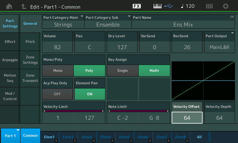
This is found as a Part COMMON parameter within the Performance. You have a similar Velocity Depth and Velocity Offset for Output level (amplitude) for the PART’s response to Velocity coming from the MONTAGE keyboard or coming IN via Midi (from a sequencer track or another controller). You will also find another Velocity offset specifically for arpeggio phrases and how they respond (just FYI).
You start to see the attention to detail that can be brought to each component within each PART.
In the tutorial article (“Winds & Strings”) on MONTAG-ifying Motif XF Performance data, we saw (and heard) how the Velocity Depth and Offset were used to allow the Woodwind sounds to play at lower velocities and the String PART only came in when we played with increased gusto. It can be set to be as subtle or as obvious as you desire. Please see this article for a practical application of the Velocity Depth and Velocity Offset as applied across all the Elements of a PART.
Velocity Offset/Depth Experiments
The standard “linear” velocity curve (normal) would be for each increment of effort you increase the key-on velocity 1-127, there will be increase in the MIDI Output 1-127. To get a clear understanding of how this COMMON Velocity Offset/Depth works in conjunction with the previous discussion and to fully hear the results here, please set the Element Level/Vel = +32, the Offset = 0, and the Curve = 3 for the following experiments:
These settings are your typcial settings for Element Velocity. We can more clearly hear their results when we adjust the COMMON VELOCITY OFFSET/DEPTH settings.
Say you played something into your DAW and the velocity you used or the velocity of the recorded MIDI data did not give you enough audio output, the Velocity Offset parameter allows you to increase the output result (or if you lower it, decrease, the output result).
Input effort (Key-On velocity) is the x-axis left to right.
Output result (Amplitude in the case) is the y-axis bottom to top.
A setting where both the DEPTH and OFFSET = 64 results in no change to the PART’s currently programmed input/output response.
Navigate to the PART 1-COMMON > “Part Settings” > “General” screen and lets look at the VELOCITY OFFSET and DEPTH parameter in the lower right corner. Default is 64/64:
- If you increase just the DEPTH to 127, (Offset 64; Depth 127) notice how visually it will now take half the effort (input) to reach maximum output. The y-axis reaches maximum (top) when the input (effort) reaches 64 (halfway). You should hear the sound get louder easier (with less effort):
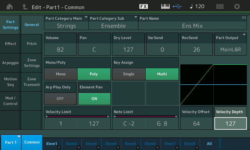
- If you decrease DEPTH below 64, (Offset 64; Depth less than 64) notice how visually you will not be able to reach maximum output any longer.
- Reset the DEPTH to 64 and experiment with OFFSET.
- If you increase just the OFFSET say to 86, notice how it takes little to no effort to reach maximum output:
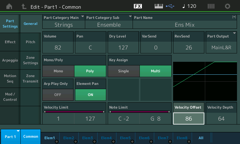
- If you decrease the OFFSET below 64, notice how visually you will not be able to reach maximum output any longer. Shown below the Velocity Offset is 49 and the green line has failed to reach the top of the graph:
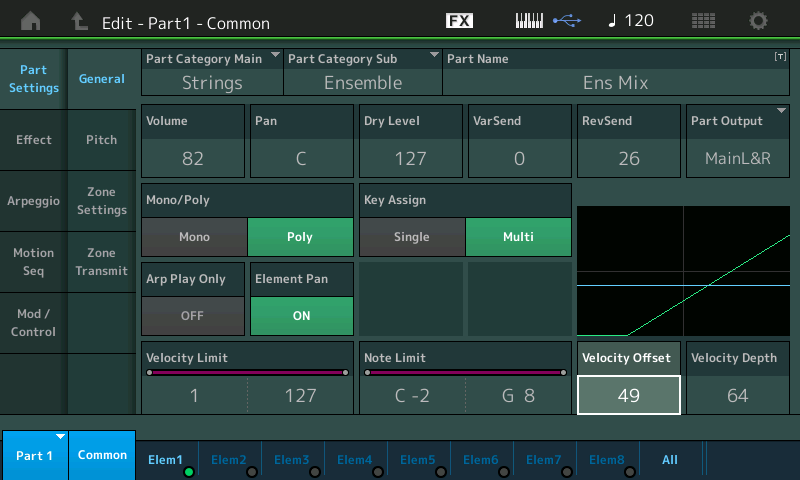
Now try this:
- Set the OFFSET = 21
- Set the DEPTH = 107:
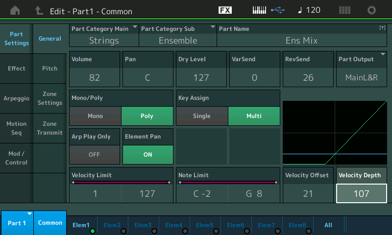
See how for very low velocities you will not get much sound output, but after a point the velocity curve is steep towards maximum.
If OFFSET = 0 and DEPTH = 127, you will get virtually no sound output until you reach a velocity of 64. You see how this can tend to be great for cross-fading. By creating a program that worked opposite this behavior.
The Velocity DEPTH and OFFSET parameters work to change the output result to incoming velocity (without having to destructively change the MIDI Event data contained in a track). You must “play the keys” with varying strength to experience the sonic difference.
Remember: changing the Velocity Sensitivity can change dramatically the performance of MIDI data – particularly in programs that depend on velocity switches within the Waveform (like a “slapped” bass program).
This PART Common Velocity Offset and Velocity Depth behaves in a similar fashion to the way in the FM-X engine. It can be applied to the FM-X sound overall. But the individual Operator functions are quite different, naturally, from those of the AWM2 Element.
FM-X and Velocity Functions
Unlike the AWM2 Engine, where each building block Element is capable of outputting sound, in the FM-X Engine, only the CARRIERs output sound, the MODULATORs influence the resulting output of the Operator it is feeding into. The FM-X Engine is not broken into the same basic building blocks as the sampled-based AWM2 Engine. FM synthesis has two types of sources Carriers which can create sound, and Modulators which can alter the harmonic content of the Carrier.
In the AWM2 you have OSCILLATOR > FILTER > AMPLITIFIER as the way sound is made, the timbre is adjusted and output. In the FM-X Engine each Operator has its own pitch and loudness generators built-in but the timbre (the role of the Filter to change the tone) is handled by the relationship and interaction between the MODULATOR and the CARRIER.
Okay, lets give a basic, simple (musical) example of this Modulator/Carrier relationship. The Carrier can be heard, the Modulator influences the resulting output made by the Carrier. In your mind, picture a violinist bowing the instrument with their right hand with bow and applying vibrato with their left hand. The right hand, bow on string, is responsible for the vibration (oscillation) that we hear as the pitch; the left hand, adding vibrato, is shortening and lengthening the active string causing the pitch modulation we musicians refer to as vibrato. If the right hand (Carrier) lifts the bow from the string, what occurs?
The sound stops. Even if the left hand continues to apply vibrato, What do you hear? You cannot hear the Modulator by itself. You only hear the modulator’s influence on the bowed string which carries the pitch! FM is based on this very concept. The Modulator and the Carrier.
So the more intense the vibrato (the Modulator) the deeper the change in tone of the resulting string sound (the Carrier). When Velocity is increased to the Carrier, the behavior is very similar to what we’ve been discussing with the AWM2 Element – that is, it gets LOUDER. But when Velocity is increased to the Modulator, you can expect that instead of a change in Volume, you will get a change in timbre/tone. The harmonic content will be different. FM synthesis is all about generating specific waveforms that contain a particular overtone (harmonic) structure.
So Velocity applied to a Carrier can change the output level, and Velocity applied to the Modulator will change the tone.
Within the FM-X Engine the “Level/Vel” parameter when set to +0 will result in being non-velocity sensitive. No change will occur due to the strength with which you strike a key.
When the “Level/Vel” is set to +7 (the maximum within FM-X) you get the maximum sensitivity – meaning that as you increase from 0 toward +7 you are increasing the amount of effort it will take to make this Operator output its signal.
When the “Level/Vel” is set to -7 (the minimum within the FM-X) you get the opposite reaction – meaning as you increase the effort to trigger a key the less output from this Operator.
Experiment:
Let’s start with an “INIT NORMAL (FM-X)” Performance:
- Press [CATEGORY SEARCH]
- Touch “Init”
- Select “Init Normal (FM-X)”
- Press [ENTER]
- On the HOME screen touch “View”
- Press [PART SELECT 1]
You should see a screen that shows you the “PART 1 Algorithm View”: where you can select Algorithm 6.
This screen shows you the 8 potential Operators each with a Fader – use the front panel Faders to control the levels of OPERATORs 1 and 2:
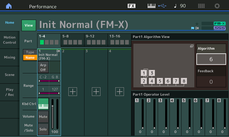
Algorithm 6 – places Operator 1 as a Modulator (top) and Operator 2 as a Carrier (bottom). This is the classic two Operator stack that is at the heart of Frequency Modulation.
This is all we will need to illustrate the Modular/Carrier relationship. OP1 moduluates OP2.
Lower both Faders 1 and 2 to minimum, then slowly raise them to maximum. Making sure the red LED indicator moves with the Fader. (You must ‘hook’ the indicator for the levels to be active).
You will discover that you can easily hear Operator 2 – all by itself, but if you raise only Fader 1, you cannot hear Operator 1. You can, however, hear the influence of OP 1 on OP2.
Raise OP2 to max, then slowly raise OP1 to max – hear the timbre change as you increase the Modulator (OP1).
Leave them both at maximum (very bright, overly modulated nasal tone) and let’s bias the output of the Modulator to Velocity – basically, make it so that only as we increase the Velocity will the timbre get bright:
- Press [EDIT]
- Touch “OP1” in the screen
-
Touch “Level” in column 1
- Set the “Level/Vel” = +7
- Now as you play the keyboard notice that you must increase the Velocity in order to make that bright, overly modulated, nasally sound
- When you have observed this set it back to +0and lets try the same with the Carrier, OP2
- Select “OP2” (you can do so in the screen or by pressing the second button in row 3 on the right front panel “Element/Operator 2”
- Set the “Level/Vel” = +7:
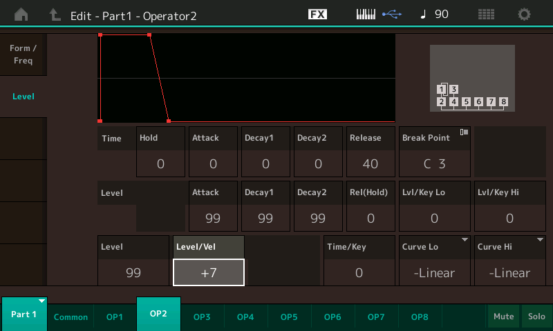
Now as you play the keyboard, notice that more effort pressing the keys increases the overall Volume of the sound. If you returned the Level/Vel of the Modulator to +0, you should hear a bright, overly modulatated, nasally sound, that increase in volume as you play harder.
Not a very pleasing tone, but great for this illustration!
Want to share your thoughts/comments/questions about this article by Bad Mister? Join the conversation on the Forum here.
Keep Reading
© 2025 Yamaha Corporation of America and Yamaha Corporation. All rights reserved. Terms of Use | Privacy Policy | Contact Us