Notifications
Clear all
MONTAGE Series Synthesizers
11
Posts
2
Users
0
Likes
4,278
Views

Topic starter
I have gone through all the tutorials so far, and the difference between unipolar and bipolar is still puzzling to me.
Take this screen shot for example:
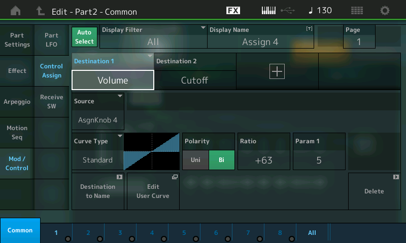
I think it would be a big help if we could get some idea of what the numbers on the axes of the curve graph might be. I suspect that the horizontal axis goes from 0 to 127 from left to right. (Am I correct about this?) What's the numeric range of the vertical axis?
Would the numbers on the axes be different if the chosen curve was unipolar instead of bipolar? If so, how?
Posted : 12/06/2016 1:41 am

I have gone through all the tutorials so far, and the difference between unipolar and bipolar is still puzzling to me.
It takes a minute to get this, I hope I can clarify.
Let's use the PERFORMANCE from the tutorial "Super Knob Morph A". The Sawtooth that morphs into the Square Wave. Fully Sawtooth when the SUPER KNOB is 0 and fully the Square when the SUPER KNOB is 127.
Recall this PERFORMANCE
Press [EDIT]
Press [PART SELECT 1/1] to select the Sawtooth Wave
Press [PART SELECT 2/2] to select the Square Wave
Get comfortable using the [MUTE] and the [SOLO] function to isolate each in turn so you can hear exactly what is happening.
Isolate just the Sawtooth (do so by lighting the [SOLO] function and touching [1/1]
As you turn the Super Knob from 0 toward 127 you will hear the Volume of the Sawtooth being reduced. The graphic shows it going from maximum (upper left corner) toward minimum (lower right corner).

The graphic indicates from the maximum to the minimum. It indicates that this sound is full on when things are neutral. And as the knob is raised the sound goes to absolute minimum.
Isolate just the Square Wave (do so by pressing [2/2] while SOLO is engaged.
As you turn the Super Knob from 0 toward 127 you will hear the Volume of the Square being raised from minimum to (lower left corner) toward maximum (upper right corner).
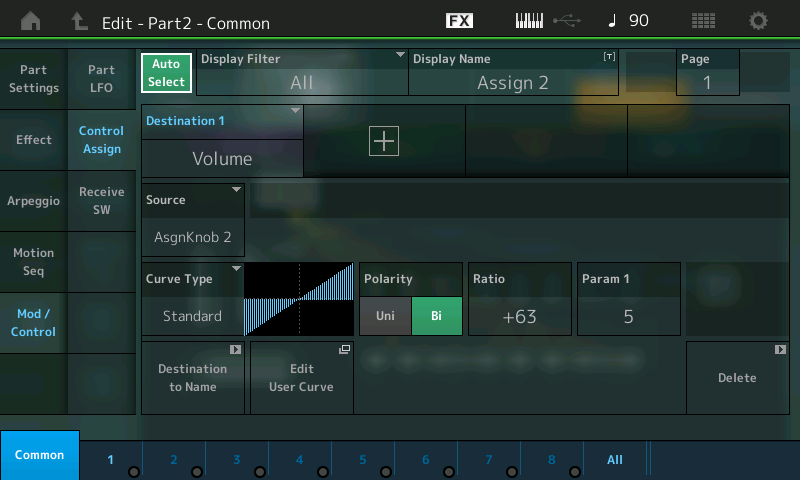
Try changing the Polarity from 'Bi' to 'Uni' on the Square Wave.
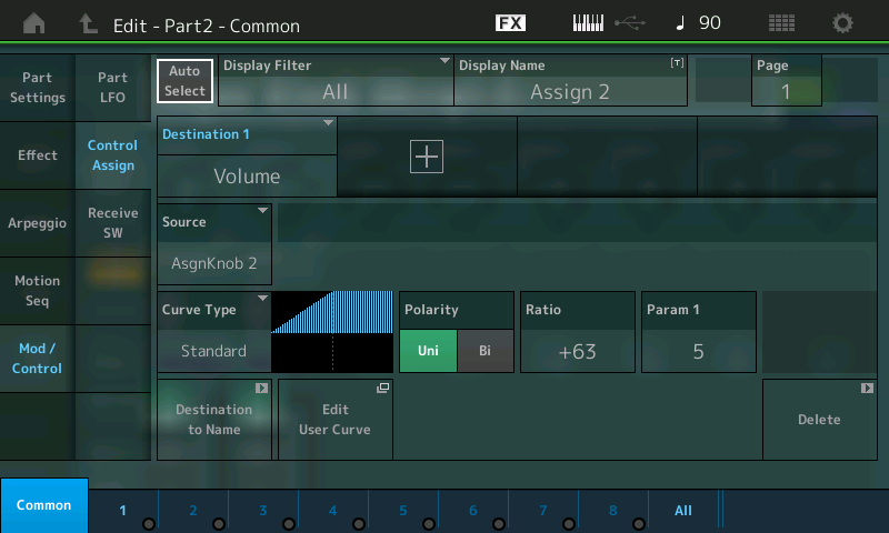
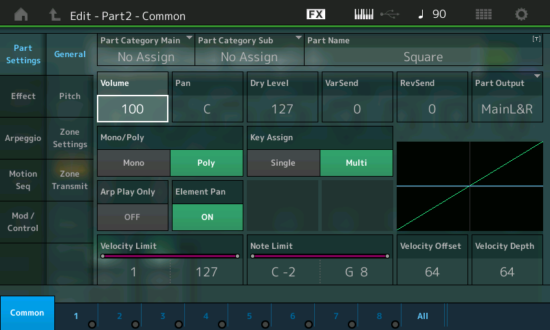
Again turn the Super Knob from 0 to 127, notice, significantly, you cannot reduce the volume to 0. You can only reduce the VOLUME to the value set by the PART VOLUME. This is not a bad thing, it is actually useful in another situation (where you want to set a minimum value from which to start). In this particular example, the PART VOLUME is 100, you can see this by selecting "Part Settings" > "General"
The first several articles do this very thing with LFO SPEED. Go back and try those but experiment with VOLUME. If you are Uni you will turn up from the Stored value (if "+" positive); you will turn down from the Stored value if "-" negative direction is selected.
In this "Super Knob Morph A" the minimum Volume is set by the main PART Volume. If the main PART Volume is set to 127 then you would not be able to turn the Volume down with the Super Knob... because the minimum 127 is equal to the maximum 127.
You would have to set the PART VOLUME to 0 in order to have UNI control the full range! Try it!
You would be better to use Bipolar because the PART VOLUME starts at particular positive value 100, by using the Bipolar curve we are able to go higher *and* lower, we are able to start with the PART turned down, and we are able to turn it up to maximum.
Rather than starting at the stored value and moving in one direction from there (the definition of 'Uni'). Play with it - it will come clear the more you experiment. Re-do the first couple of "Unipolar" article examples... They start with the "LFO Speed" set some where in between the min and max of the range (just as this volume did), you noticed we could only turn it up from the stored value and when we return the Super Knob to 0 the speed returned to .21Hz... In order to do ”full range" with Uni we had to set the LFO Speed to 0.00Hz. If you review the early article on Unipolar - it will become clear.
We used LFO SPEED in the early articles, this example (Morph) uses Volume, but the parameter is only the parameter - the behavior is the same. If you want to go above and below the stored value, Bipolar is the choice. You could use Unipolar but then you must set the parameter to set minimum
In general, when you need to go in two directions above and below the current or normal value, you'd use bipolar. If you need to move in just one direction from the stored value you'd use bipolar.
You're thinking correctly, just not applying to actual use case. Experiment with the Part Volume, as I outlined above. It will fill in some of the blanks about the Part Volume slider and the Super Knob controlling Volume. You've noticed that some times the Part Volume fader is at 0. (If Uni is assigned, and set to control Volume, you can bet it's full range control.)
The numbers on the graphic would "kind of" help but would need to somehow show the stored value as well. Using your ears would tell you more. Too many potential parameters and scales because there are so many parameter destinations.
I think the point is that with Unipolar (with the Standard curve) you can move in one direction, only. So if the LFO setting initially was .21Hz on a scale that ran from 0.0Hz thru 39.7Hz... Best you can say is it is some where in between the absolute minimum and the absolute maximum. The setting .21Hz meant that even with the Super Knob at 0, there was movement.
Because the Part Volume is set at 100, this becomes the minimum and 127, of course, is maximum. If you use 'Uni' you will be forced to set Part Volume to 0 to control the full range.
So Unipolar can be used to control fading in or fading out. But how it impacts the stored value, is one thing you consider when choosing Uni or Bi. Do you need to move full range, do you need to move both higher and lower from the stored condition, or is simply moving in one direction and back sufficient?
If you choose Uni, then the stored value is your staring point; a point from which you can move in one direction (standard curve). The stored setting plays a role.
If you choose Bi, you then can cover the full range or not, using the Ratio setting within Curve control setup.
Hope that helps.
Posted : 12/06/2016 2:18 am
Topic starter
It helped a lot, Bad Mister. I understand the difference now. I can even look back at other things you said previously and see how you were telling me the same thing, but at that point I just didn't get it. The tech support we get from you and others around here is wonderful. Thanks!
I have two more questions that will help me nail down my understanding of this area.
PROGRAMMING BASICS 7: SUPER KNOBS VALUES says:
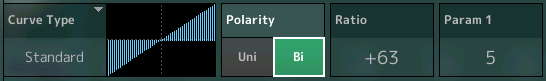
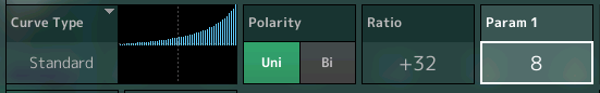
The CURVE is Standard; The POLARITY is Bi; the RATIO is set to +32, which enables full parameter control when the KNOB is moved minimum to maximum.
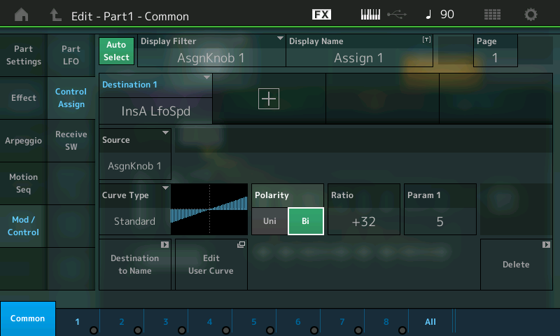
But the curve graph only goes halfway down on the left side and halfway up on the right side. I would have thought that "full parameter control" would occur if the RATIO was set to +63, so that the curve graph would go from all the way down on the left to all the way up on the right. How does a setting of +32 provide full control?
My other question: is there anyplace in the user interface where you can see the actual numeric value of a parameter that's being controlled by the Super Knob (or by some assignable knob)? In other words, if I have the Super Knob controlling the volume of Part 1, is there someplace where I can see the actual numeric volume setting in real time? I think being able to see that would be really helpful to me as I check the way I have things set up. I've looked around, but so far haven't found a place that shows me this.
If there isn't such a place in the user interface, I think it could be a good suggestion for inclusion in a future firmware update.
Posted : 12/06/2016 6:52 pm
Okay, glad it is helping. And thanks for the questions because others are being helped as well.
But the curve graph only goes halfway down on the left side and halfway up on the right side. I would have thought that "full parameter control" would occur if the RATIO was set to +63, so that the curve graph would go from all the way down on the left to all the way up on the right. How does a setting of +32 provide full control?
With the RATIO value set to +32; and the Polarity set to Bipolar, as you move the Super Knob from 0-127 you reach a maximum at +32... Increase it (the RATIO) from +33 through +63, notice it does not get any faster, maximum is reached at +32. This is the same as it was in Motif series. A curve setting of +32 gave a unit increase in output result for each unit increase in effort (input) for values starting at absolute minimum.
Values above +33 I can best explain on a one directional curve, say velocity. If a velocity curve is set to +32, this means an input effort of 50 (on the 1-127 scale) would result in an audio level output of 50 (on that 10127 scale). An input effort of 120 would result in an audio output of 120. But if you were to raise the RATIO above +33 you would notice that low velocities would have "no effect", at all, instead low input values will have hardly any effect at all. By the time you reach +63 only a very strong key strikes cause any output at all. All other values produce 0 output... used for crossfading. Only a very strong key-on velocity produces any output.. So +32 is the linear response, +63 requires the utmost input to get any output at all.
In the "Super Knob Values" article, Bipolar is used to change LFO Speed, the point at which the graphic crosses the centerline (in the middle of the graphic) is exactly the spot where 2.61Hz is reached (that is the Stored speed value = 2.61Hz). The graphic is linear from there until it reaches the maximum speed. Turning the Super Knob from centerpoint to the left (counterclockwise) turns the speed here from 2.61Hz down to 0.00Hz.
So again, Bipolar is used when you will be turning the Destination both above and below the stored value. The stored value is 2.61Hz, the minimum is 0.0Hz, the maximum is 39.7Hz. (Bipolar resembles Uni - if you start from the centerline and go to the right).
Experiment for full understanding: On this example, navigate to the Part 1 -Common - Effects - INS A
Change the LFO Speed from it 2.61Hz setting to 0.0Hz.... Making the stored value 0.0 Hz. Now when you turn the Super Knob you will get no change until you reach the centerpoint (two sets of LED indicators appear at the apex of the Super Knob). Values from minimum to halfway all equal 0.0Hz. And moving the Super Knob from midpoint to maximum only gets you about halfway to maximum speed... Now in order to get full range you must increase the RATIO to maximum, "+63". So now the range min-to-max is achieved from 12 o'clock to 5 o'clock. What actually parameter value that is, will depend on the RATIO.
So half the movement of the Super Knob 7 o'clock to 12 o'clock does nothing, and the movement from 12 toward 5 o'clock now does not cover the full range until you increase the Ratio to +63!
If this was volume - it's just like all values for volume less than 0 equal no volume. Hope that makes sense.
My other question: is there anyplace in the user interface where you can see the actual numeric value of a parameter that's being controlled by the Super Knob (or by some assignable knob)? In other words, if I have the Super Knob controlling the volume of Part 1, is there someplace where I can see the actual numeric volume setting in real time? I think being able to see that would be really helpful to me as I check the way I have things set up. I've looked around, but so far haven't found a place that shows me this.
The values that are assigned to movement of the knob do not animate by moving the Knob. If you want to "see-and-hear" the values change simultaneously, highlight the actual Destination parameter and move it using the DATA DIAL.
There are simply too many Destination parameters for them to all animate under control of the assigned controller, trust me. The Performance Common has 24 knob parameters plus 8 assignable knobs, each of the sixteen Parts has 24 knob parameters plus 8 Assignable knobs... times sixteen Destinations in each PART. 8 of those 16 Parts can be under simultaneous keyboard control, all these parameters animating would probably cause a sluggishness. Besides you set these things by ear... At the end of the day, you really want to "see" the stored value when you navigate to the parameter location.
If you want to "see-and-hear" the response of the Destination parameter, highlight the Destination parameter directly and use the DATA DIAL to manually change the value - this will give you the opportunity to both see-and-hear the full range of the parameter, and select its start point. (I'm quite sure I covered this very thing in the articles... Including the fact that the parameters assigned to the knobs do not animate. It is actually more useful to see the "stored" value, you will obviously hear its current status... As you move your selected controller. I think if you go back and read them again, connecting the dots will improve (there are times you want to have the stored value something other than 0, this is where Bipolar is very useful - it means you can move in either direction from that stored value).
Hope this helps tie it together. In general, if the stored value is "in between" the absolute minimum and maximum, you will be able to turn up and/or down with the Bipolar selection. Unipolar assumes you are going in only one direction from the stored value!
0.0 Hz = Super Knob at 0
2.61Hz = Super Knob at center (stored value is somewhere "in between"
39.7Hz = Super Knob at 127
Posted : 13/06/2016 11:41 am
Topic starter
That was the rest of what I needed. I've got it nailed now. I can set things up and they work just the way I thought they would.
But speaking as someone who has been professionally designing graphical user interfaces since the 1980s, I'd like to point out what I consider to be a serious flaw in the user interface for Bipolar curves. (Unless I'm mistaken in my understanding. If I am, that's fine with me; I'll just learn something else useful.)
A Ratio of +32 gives you "full control" of a parameter. But the curve doesn't look like that's what will happen. What the curve shows is that turning the knob that controls the parameter from 12:00 (i.e. top dead center) all the way counter-clockwise would get you halfway to the minimum possible value, and turning it from 12:00 clockwise would get you halfway to the maximum possible value. I now understand, and have verified for myself on my Montage, that you actually go all the way down to the minimum possible value and all the way up to the maximum possible value when the Ratio is set to +32. But the curve does not show this.
This is what I think the curves for Bipolar should actually look like for positive Ratio values (and similarly for negative Ratio values):

These curves illustrate what actually happens. When Ratio is set to +63 and you move the knob from 12:00 clockwise, the first half of the rotation increases the controlled parameter to its maximum value; the second half of the rotation keeps it at that maximum value. This is exactly what the curve I'm proposing shows. The actual curve on the Montage for a Ratio of +63 looks like my picture for +32, which does not match the actual behavior of the Montage.
I think this would be a great candidate for a firmware update. And I think it would be good to do it quickly, while there are not very many Montage owners who could potentially be confused by the change.
I think it's odd that Yamaha got the Unipolar curves exactly right and still got the Bipolar curves wrong, but there we are…
Posted : 14/06/2016 12:58 am
Topic starter
The goal in user interface design (which is often not completely achievable) is to make things so obvious that no explanation or manual is required. Here's what might be a better idea for making the curve graph user interface more user-friendly.
There's plenty of room in the user interface to add two new fields:

The idea is that these fields would give you a view of the relationship between the knob and the controlled parameter. You would see both numbers updating in real time as you turned the knob.
This next idea for the curve graph would make the relationship between a knob and the parameter it controls more obvious. Let's say that the stored value of a particular parameter is -32, and we set a Bipolar curve for it with a Ratio of +32. Here's what I think that curve graph ought to look like:

As the knob was rotated from 0 - 127, the parameter value would start at its minimum and rise to -32 as the knob value hit 64. Then it would rise more quickly from -32 to its maximum value as the knob continued past 64 to 127.
As I understand things now, this is how the relationship between a knob and a parameter works. It would be good for the curve to reflect that actual behavior instead of showing you a straight line which falsely implies that the rate of change is equal over the entire rotational range of the knob.
I should also say that I think the Montage user interface is a huge advance in usability over the Motif XF. It feels like you're so much closer to the machine, and interaction with it is so much easier and more natural. I really admire what Yamaha has done with the Montage. I'm making these suggestions in the spirit of trying to be helpful to improve what is already a great new synthesizer.
Posted : 14/06/2016 6:08 pm
Topic starter
Bad Mister, I'd appreciate it if I could get some feedback from you on what I said above about the bipolar curves. If you think I got it right, then I'll know that I actually understand what's going on. And if you think I got it wrong, then I'll learn something important.
Also, if I did get it right, I'm curious whether the information got passed along to the engineers, hopefully to include in some future firmware release.
Posted : 01/08/2016 2:00 am
I'm not at all sure it is just that simple, here's why... You are predicating your graphic on the maximum actually being reached - I don't think that is a fixed variable in this.
I'm sure its not because there isn't room on the screen for more parameters, however. 🙂
I think your stumbling block is the stored value. The graphic on the Montage screen is to show the selected Curve type and give the direction and incline of parameter change. The Knob you are turning (if it is the PART AssignKnob) will update to the proper value if you need a visual reference. If you then link this assignment to the Super Knob, well a whole other level of movement and scale is introduced.
Breaking down what you asked about I think the missing piece is that when the parameter has no negative it's tricky. For example, there are no volumes below 0. So the negative/negative (lower left) quadrant is not really there.
Here's a better way to understand.
Call up a single PART program
Let's set the VOLUME of the PART to 0 so that we can eliminate thinking about this "stored" value until last.
By setting it to 0 we will be using the graphic alone to display what is happening to output level.
Press [EDIT]
Press [PART SELECT 1]
Press the lower [COMMON] button
Touch "Part Settings" > "General"
Set the VOLUME = 0
Touch "Mod/Control" > "Control Assign"
SOURCE = ASSIGN KNOB 1
DESTINATION = (Part) Volume
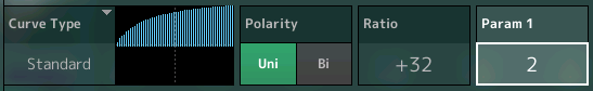
Setup a CURVE using the "Standard" option:
Select UNI for Polarity
Set the RATIO = +32

As you turn the AssignKnob1 from minimum to maximum you hear a smooth increase from minimum to maximum. Notice the graphic starts at the 0 center line and extends to the upper right corner. That is 0 through 127 for volume, there are no negative volume values. So volume is a parameter on this graph that travels from the center line up, like this:
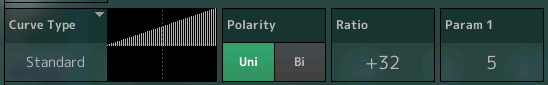
If you turn the AssignKnob1 from min-to-max, it represents an increase continuously from start to finish
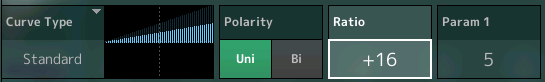
If you reduce the Ratio value to "+16", you will notice that even when you turn the AssignKnob to maximum you only get about half the output. So maximum output is not always ensured... it depends.
Turn the Ratio to +0 obviously no matter where the AssignKnob is placed there is no output, and for all negative values (so why are they there?) because if the "stored" volume was a positive value - going negative would turn it down. We'll come back to that "stored" volume.
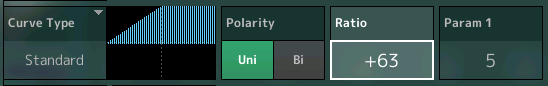
If you increase the RATIO to maximum +63, as you turn the AssignKnob1, you will reach maximum output by the time the knob reaches 12 o'clock. at about halfway through - all values above that are the same output.
Change the Polarity to "BI" leaving the Ratio at +63
As you turn the knob from minimum to maximum, see how there is no volume until you reach 12 o'clock, and the full volume changes takes place between halfway and maximum. You cannot hear negative volume!
Okay, now, as you can tell this is how the knob moves through these settings. If you want to change the ramp/slope from anything but a straight line on the "Standard" Curve you will need to introduce the PARAMETER 1 - as you can see above all are at the center setting of 5... as you increase PARAMETER 1 you delay the increase ramp/slope; and as you decrease its value you ramp up earlier.
Back to the initial "stored" volume, we set the PART PARAMETER Volume to 0 when we began so it would not interfere with your understanding of these graphics and the movement of the KNOB. The stored volume simply is a number along the way and does not change the graphic Curve or its response; What it does is it determines whether or not you are hearing any sound when you reach minimum or approach maximum. Because instead of the 0 line being silence, the stored volume is an offset from that. And silence and performing maximums are things best set by ear (not eye).
You select "UNI" if you want to move in just one direction from that stored point. Say you only need to turn up from there; or you only need to turn down from there... but not both. "UNI" is your choice.
You select "BI" if you want to move in both directions, both above and below the stored volume. There is no guarantee of maximum volume is reached at the top end, nor is there a guarantee of silence when minimum is reached, ... it depends on the initial setting you choose and the Curve applied. Just as the volume does not always reach maximum when you turn up, so it is also true that silence is not always the result when you turn things down.
I do not think that having the controlled parameters animating in the screen is really going to help, at all, with the understanding. It is really about relating to the change you hear (seems like an awful strain on the CPU with little return). The physical knob is in one hand and has a lighted indicator - that should suffice, I believe.
Hope that helps a bit...
Posted : 01/08/2016 5:59 pm
Topic starter
I just tried all the things you described in your most recent post. Everything checked out just as you said, except for this:
I set up a single-PART program so that Assignable Knob 1 would control its volume like your diagram showed:

I set the Volume parameter of the PART to 64. Then I held a key down and turned Assignable Knob 1 and listened.
With the knob all the way counter-clockwise, there was no sound. There continued to be no sound as I rotated the knob clockwise to the 9 o'clock position. From 9 o'clock through 3 o'clock, the volume of the sound increased steadily from zero to maximum volume. And from 3 o'clock to all the way clockwise, the volume stayed constant at its maximum value.
This is consistent with the leftmost diagram I drew above. It's not consistent with the graph displayed by the Montage for Ratio +63.
In an earlier post in this thread, you described how Velocity would be reflected in a linear fashion when the Ratio was +32. That seems correct to me. But the Montage displays the linear graph when the Ratio is set to +63. With Ratio set to +32, the Montage displays a graph that goes from half-minimum to half-maximum.
I'm perfectly prepared to be wrong about this. I wouldn't mind at all. But so far, this is what I'm seeing and hearing...
Posted : 04/08/2016 4:25 am
You start out on the wrong foot right here:
"I set the Volume parameter of the PART to 64. Then I held a key down and turned Assignable Knob 1 and listened."
Again, the reason I suggested you set the Part Volume to 0 was to eliminate your confusing that "stored" value as something significant. It has little to do with the Knob position and the parameter value change.
We are focusing in on the AssignKnob movement and the graphic on the screen. So again do not ignore my suggestion to set the PART Volume to 0.
With the volume at 0 the position of AssignKnob represents the result you are hearing.
You seem to want to bring in the "stored" volume. The graphic on the screen in question is how the AssignKnob is applied to the parameter.
Posted : 04/08/2016 3:44 pm
Topic starter
Thanks, Bad Mister. I took your advice and started out on the right foot this time. I put together a one PART performance that has Assignable Knob 1 controlling the Coarse Tuning of a simple waveform. It's Bipolar, and the Ratio is +63. Coarse Tuning has a stored value of 0.
Turning Assignable Knob 1 produces a steady pitch change across the entire rotational range of the knob.
So I was clearly wrong in my previous "understanding" of what's going on with Bipolar polarity. But I understand it now.
Thanks for your help getting me off the wrong track. If you're not already tired of this topic, I'd be interested in an explanation of how Bipolar works when the stored value is not 0.
I've attached a library file containing one Performance -- the one I used to verify the behavior of Bipolar polarity. The Performance is called Bipolar Tune Asgn1. I set it up so that the Super Knob controls Assignable Knob 1, so either knob can be rotated to hear the pitch change.
Posted : 05/08/2016 1:09 am
