We take your Privacy very seriously.
Part IV
In Part 2 of this series, we learned that all sounds change over time. No sound, after all, lasts forever, so at a minimum, its volume (amplitude) must eventually fade to nothingness. But it’s not just amplitude that changes. Virtually every naturally occurring sound also undergoes a tonal (timbral) change during its existence, and some exhibit a degree of pitch (frequency) change as well. In this installment, we’ll examine the digital FM tools that allow you to create these kinds of sonic variations.
First, though, let’s take a closer look at the ways that sounds typically change over time.
How Sounds Change
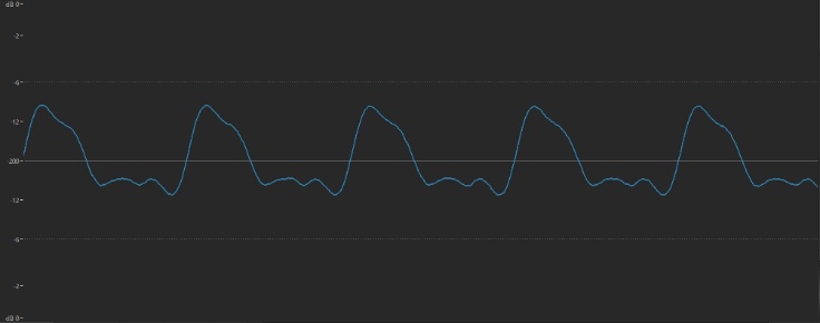
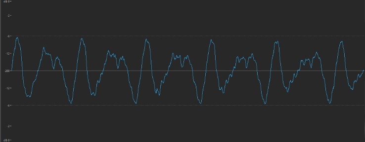
In Part 2 of this series, we showed you the waveforms for three instrument sounds: Flute, guitar and cymbal.
Here’s what they looked like. First, flute:
This is what guitar looks like:
And here’s the waveform for a cymbal:
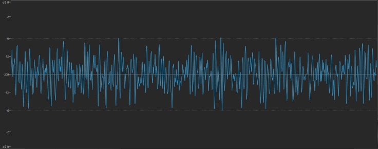
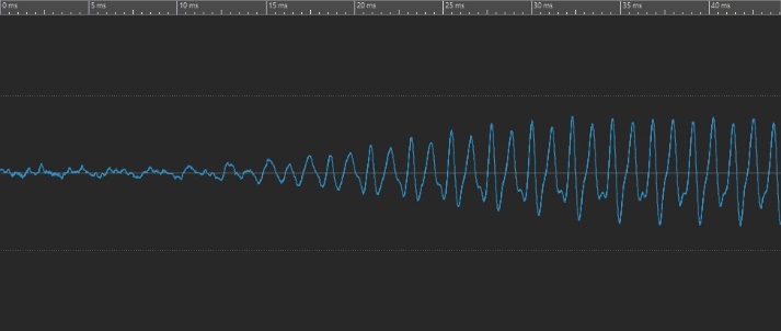
As you can see, each wave has its own distinctive shape, reflecting its timbre (i.e., its overtone makeup), and clearly each of these three instruments has a different timbral complexity—with flute having the fewest overtones and cymbal having the most overtones. But each of these images only shows the waveform at one particular moment in time—in these cases, a half a second or so after the sound was produced. Let’s take a look instead at these same waveforms, zoomed in so we can see the first 40 thousandths of a second (that is, the first 40 milliseconds, or ms) of their existence. Here’s what the very beginning of our flute sound looks like:
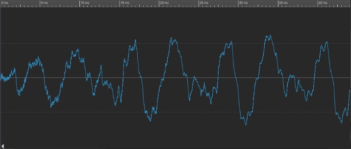
Here’s what the very beginning of our guitar sound looks like:
And here’s the very beginning of our cymbal sound:
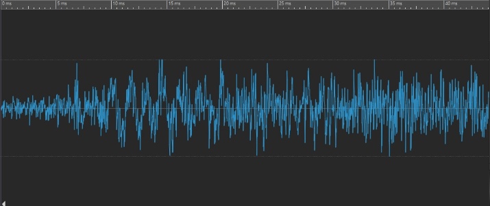
If you compare these to the waveforms in the first three illustrations, you can see there’s quite a difference!
Now let’s zoom out and take a look at a longer chunk of time. For example, here’s what the first full second of the flute sound looks like:
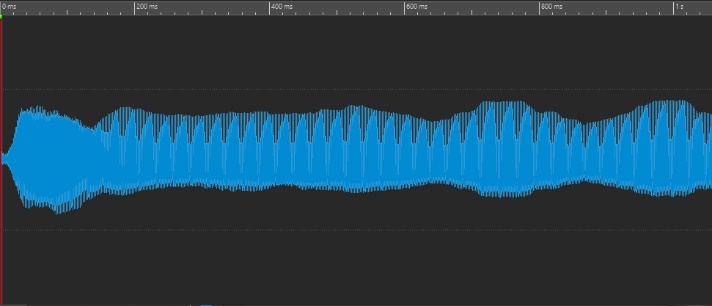
Here’s what the first full second of the guitar sound looks like:
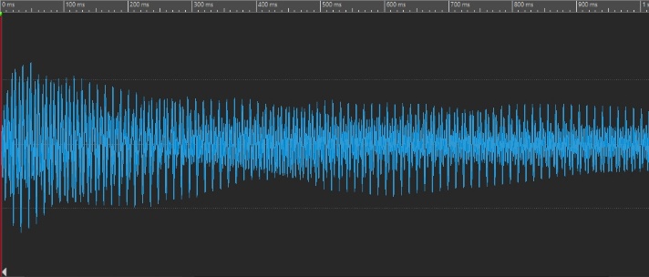
And here’s what the first full second of the cymbal sound looks like:
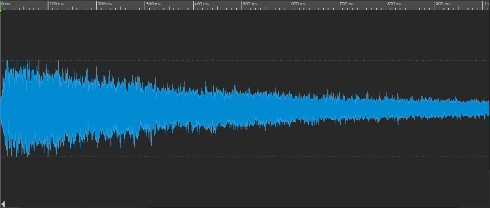
Clearly, the amplitude of each is changing over time. In the case of the flute, it’s actually increasing; in the case of the guitar and cymbal, it’s decreasing (though more rapidly in the cymbal than in the guitar). But the timbre is changing too, as we’ve just seen: the beginnings of each of these sounds exhibits a distinctly different waveform than the same sound a tenth of a second in.
Now that you’re aware of these changes, you’ll find that you can clearly hear them too. Listen to these three audio clips and focus in on how the sound changes volume and timbre over time:
These kinds of changes are not restricted to musical sounds; most non-musical sounds also change timbre as well as amplitude. Think of a crack of thunder or a wave crashing on the shore: in each case, there’s a loud explosion, followed by a low rumble.
As mentioned previously, some sounds exhibit a pitch change (that is, a change in frequency) too, though this is usually far more subtle than amplitude or timbral change. Hard-plucked guitar strings, for example, go slightly sharp at first—something you may have noticed if you’ve used a tuner. The same occurs when you blow harder into most wind instruments. Again, this is not limited to musical sounds—for example, both a gale-force wind or a babbling brook undergo numerous pitch changes throughout their duration, all clearly audible.
So, to summarize: All sounds undergo an amplitude change throughout their duration, and most undergo a timbral change as well; some also exhibit a change in pitch too. Now that these basic principles are established, let’s take a look at the component in a digital FM synth responsible for imparting such changes: the envelope generator, or EG for short.
The Envelope Generator
For most of the rest of the world, the word “envelope” is associated with a paper wrapper that contains a letter. But in synth-speak, the word stands for “something that imparts an aperiodic change.” The word aperiodic simply means “once only,” as opposed to a repetitive (periodic) change, such as, for example, a modulator sending signal to another operator, or an LFO—short for “Low Frequency Oscillator”—a hardware or software device provided by most synths (including digital FM ones) to impart a regular vibrato, tremolo or other kind of repeating musical effect.
In Part 2, we described the three components of the operator: the oscillator, the amplifier and the envelope generator. You may recall that this is the way they’re interconnected:
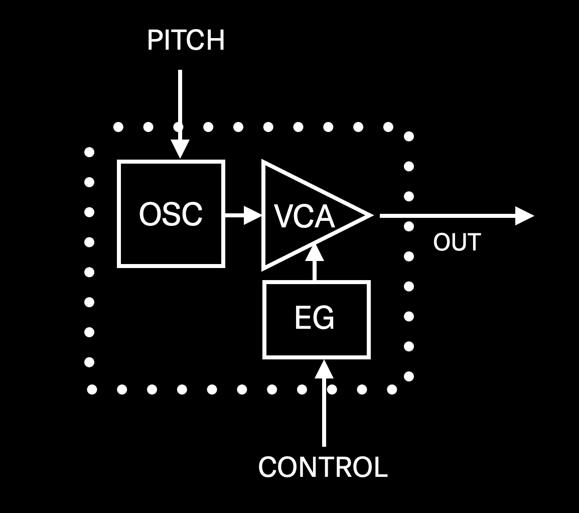
As you can see, the signal starts with an oscillator (same as it does in analog synths); it’s then sent into an amplifier, under the control of an envelope generator. Of course, an operator doesn’t decide on its own when to start playing, nor does it decide what pitch to play—those decisions are made by you, via the pitch and control signals that are generated by your synth’s keyboard when you play a note (or notes), or by an external MIDI device (such as a MIDI sequencer or external MIDI controller), or both. As you can see, the pitch input is routed to the oscillator, telling it what frequency to play, and the control signal is routed to the envelope generator, telling it to start controlling the amplifier. This brings us to our first two FM rules:
FM RULE 1: An operator doesn’t do anything until it receives both pitch and control signals; and
FM RULE 2: The amplifier within an operator doesn’t pass any signal until it is instructed to do so by its envelope generator.
Clearly, then, the envelope generator is in charge of when output signal leaves an operator, and how quickly it does so. In many ways, it’s like an invisible hand changing the operator’s Level parameter according to your instructions.
An FM-X envelope (as implemented by modern FM synths such as MONTAGE or MODX) is displayed as a series of lines interconnecting six red boxes:
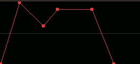
As shown in the illustration below, the vertical axis represents level, and the horizontal axis represents time. The red boxes represent four different levels: Attack, Decay1, Decay2, and Release (Hold), with values that can be set from 0 (minimum level) to 99 (maximum level). And the lines interconnecting them represent four different times (i.e., rates of speed): Attack, Decay1, Decay2, and Release, with values that can be set from 0 (fastest speed) to 99 (slowest speed). (Note that this works opposite to the way that rate-based EGs—like the ones provided by the original DX7 and other early digital FM instruments—did. In those EGs, higher values resulted in faster speeds, while lower values resulted in slower speeds.) In other words, a “Time” represents how long it takes an envelope to get somewhere, and a “Level” is its intensity when it arrives.
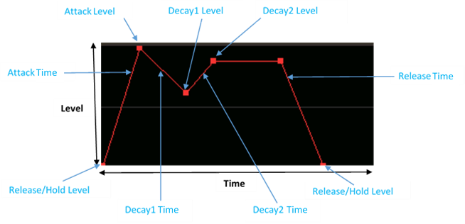
Let’s trace the journey of this envelope generator. When you depress a key on your synth’s keyboard, a Note On signal is generated. This is sent to the EG (as well as to your instrument’s MIDI output, so that other connected instruments can know you just played a note), which begins rising to whatever Attack Level you’ve set, at a rate determined by the Attack Time you’ve set. Once it arrives at the Attack Level, it continues on to the Decay1 Level, at a rate determined by the Decay1 Time. From there, it travels to the Decay2 Level, at a rate determined by the Decay2 Time. It then remains at the Decay2 Level until you let go of the key, at which time a Note Off signal is generated (this is also sent to your instrument’s MIDI Output, though more usually as a Note On event with a velocity of 0, for reasons that fall outside the scope of this article). Once that Note Off signal is received (which takes less than a thousandth of a second), the EG begins its final journey, on to the Release/Hold Level, at a rate determined by the Release Rate.
This is somewhat similar to the ADSR (short for “Attack/Decay/Sustain/Release”) envelopes offered by most analog synths, but with a greater degree of control. ADSRs offer a single decay level and time, whereas FM-X envelopes offer two of them (Decay2 is the equivalent to an ADSR Sustain level). In addition, ADSRs can typically only ever have a final level of 0 output, whereas FM-X envelopes allow the Release Level to be a value greater than 0 so that the sound can continue even after a Note Off is generated and the Release Time is complete. (In such cases, the Release Level is actually acting as a Hold Level, which is why it’s called “Release/Hold Level.” Note, however, that even if you set the Release/Hold Level to a value greater than 0, the EG assumes an initial starting level of 0.) Last but not least, FM-X envelopes provide a Hold Time, which delays the onset of any EG activity until some user-designated time after a Note On occurs. (A word of caution: setting the Hold Time to its maximum value of 99 will result in a very long delay—nearly a minute and half in length!)
Before we move on, a quick word about sustain, and how it relates to musical instruments, because all instruments fall into one of two categories: sustaining or non-sustaining. Sustaining instruments are capable of producing a sound indefinitely, so long as the stimulus for the sound is present; non-sustaining ones cannot. Wind and reed instruments, for example, are all sustaining: as long as you continue to blow into them (or introduce air into them by means of bellows or electric motors, such as accordion or pipe organ), they produce sound. String and percussion instruments are all non-sustaining. It doesn’t matter how long you hold down a piano note (even if you have the “sustain” pedal depressed)—the sound will eventually die away. This is of great importance when you’re trying to synthesize the sound of musical instruments. If you’re trying to replicate a wind or reed instrument, you should set the sustain level (or, in the case of modern FM instruments, the Decay2 level) to a value greater than 0. If you’re trying to replicate pretty much any other kind of musical instrument, the Sustain/Decay2 level should be 0. Of course, if you’re trying to synthesize a non-musical sound you can set Sustain/Decay2 however you like!
Carrier Envelopes
If you’ve been doing all the exercises in Part 2 and Part 3 of this series, a logical question you might be asking about now is, “Okay, so if these envelope generators control the output so thoroughly, how come I haven’t been able to hear their effect?” The answer is that, up until now, we’ve limited ourselves to working with Performances that all originally derived from the “Init Normal (FM-X)” MONTAGE/MODX preset, and the default envelope for all operators in that Performance is purposely unobtrusive. What do we mean by that? Well, they say a picture is worth a thousand words, so better to take a look at it than to describe it. Just follow these simple steps:
- Call up the “Init Normal (FM-X)” Performance, as described in Part 2.
- Press [PERFORMANCE]
- Press [EDIT]
- Press [PART SELECT 1/1]
- Touch the OP1 tab at the bottom of the screen or press the [MOTION SEQ SELECT 1] button
- Touch the Level tab on the left-hand side of the screen. Here’s what you’ll see:
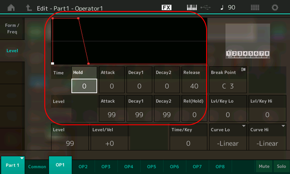
The area circled in red in this screen displays all the controls for Operator 1’s EG: five different times (including the aforementioned Hold time, highlighted here) and four different levels. Above them is a graphic representation of the shape of the envelope they form, and as you can see, it’s a big nothingburger: essentially just on/off, with a slight fadeaway after a key is released. The explanation for this totally boring shape lies in the settings of the times and levels: no Hold (0), fastest possible Attack and Decay1/Decay2 times (again, 0), short release (40), coupled with maximum Attack, Decay1 and Decay2 levels (99), with a Release level of 0.
If you touch the other Operator tabs at the bottom of the screen, you’ll see that they’re all using the same totally uninteresting envelope shape. Never mind! We’ll soon change that. In fact, let’s start by creating the actual envelope we showed you earlier. Here’s how:
- Call up the “Part 3_01” Performance you created in Part 3 of this series, or download it from SoundMondo. (This is the same as “Init Normal (FM-X),” but with the reverb turned off, Algorithm 67 selected, and the levels of Operators 1 and 2 set to 0 and 99, respectively.)
- Press [PERFORMANCE]
- Press [EDIT]
- Press [PART SELECT 1/1]
- Touch the OP2 tab at the bottom of the screen or press the [MOTION SEQ SELECT 2] button (remember, in Algorithm 67, Operator 2 is acting as a carrier)
- Touch the Level tab on the left-hand side of the screen and enter the following envelope values for Operator 2:
- Times: Hold = 0; Attack = 55; Decay1 = 70; Decay2 = 40; Release = 65
- Levels: Attack = 99; Decay1 = 60; Decay2 = 90; Release/Hold = 0
- Save this Performance, naming it “Part 4_01.” (You can also find this Performance at the SoundMondo website by clicking here.)
Now play a note, hold it for ten seconds or so, then let go of the key, listening carefully as you do so. Tonally, all you’ll hear is a simple sine wave (since the output level of all operators except Operator 2 is 0), but its volume is now changing over time as Operator 2’s EG makes its journey from the inception of Note On to its final Release/Hold Level. Specifically, you’ll hear the sound fade in slowly, then die away to a lower level a bit more rapidly before suddenly reappearing again. When you release the key, the sound then fades away slowly again.
On its own, this sound is perhaps not all that interesting, but play some held arpeggios (for example, with the root held down while adding in other chordal tones) and you can get some lovely soft chiming effects. And of course, there’s so much more editing you can do to it!
As a reminder, here’s what that envelope shape looks like:

… and here’s what the actual waveform of the sound we just constructed looks like, zoomed out to show the entire ten seconds of its existence:
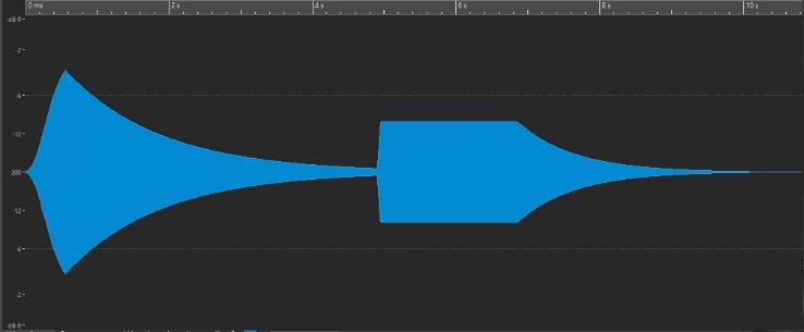
Clearly, you can see how the change in actual amplitude in the waveform mirrors the levels “mapped out” by the EG diagram—in other words, the reality matches the abstract representation.
Now it’s time to discuss a new FM rule:
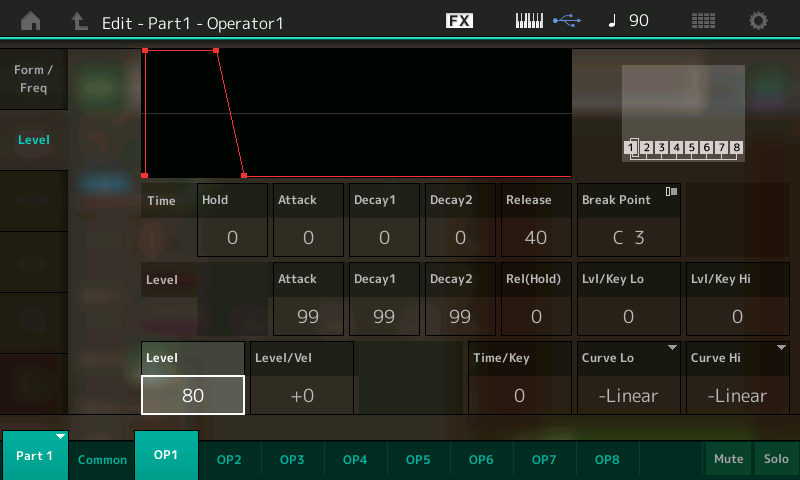
FM RULE 3: An envelope can never increase the output of an operator beyond its set Level.
For example, if you set an operator’s overall Level to, say, 80 (in the Level parameter box, highlighted in the illustration below), an EG Attack, Decay1, Decay2 or Release/Hold level of 99 will only result in an output level of 80. In other words, an EG Level of 99 simply raises the output of the operator to its set maximum (in this case, 80).
Modulator Envelopes
Since the level of carriers determines the overall amplitude (volume) of the sound, it’s obvious (as we just heard) that the EGs in carriers affects volume too. But what is the effect of the EGs in modulators? If you guessed timbre, you’d be absolutely right, as we’re about to discover:
- Call up the “Part 4_01” Performance you just created, or click here to download it from Soundmondo.
- Press [PERFORMANCE]
- Press [EDIT]
- Press [PART SELECT 1/1]
- Touch the OP2 tab at the bottom of the screen or press the [MOTION SEQ SELECT 2] button
- Touch the Level tab on the left-hand side of the screen
- Let’s start by giving Operator 1’s envelope generator the same settings we entered for Operator 2 when we created this Performance. (Remember, in Algorithm 67, Operator 1 is modulating Operator 2). The easiest way to do this is to use the MONTAGE/MODX Copy function. Accordingly, press and hold down [SHIFT], then press [EDIT]. The Copy screen will appear:
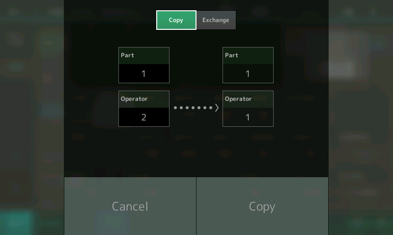
Operator 2 is listed as the source (on the left-hand side of the screen) since that is the last operator we were viewing when we initiated the Copy function. (This can’t be changed; the last Part or Operator viewed is always the source.) The destination (on the right-hand side of the screen) can be changed if desired, but it’s already populated with Operator 1 (the default), which is where we want to send the data to anyway, so just go ahead and touch Copy to complete the procedure. You’ll be returned to the Edit – Part 1 – Operator 2 screen.
- To confirm that the envelope settings for Operator 2 have been copied to Operator 1, touch the OP1 tab at the bottom of the screen. Voila! You’ll now see the exact same EG values for Operator 1 as we set for Operator 2:
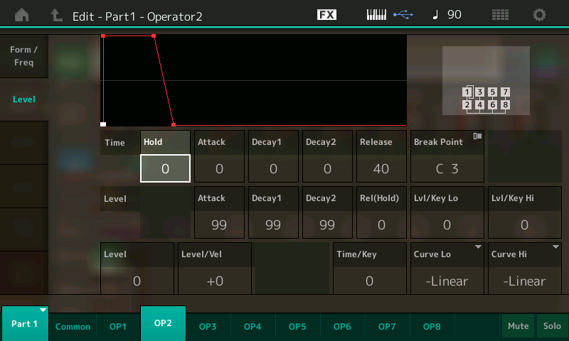
A word of caution: The Copy function copies all data from operator to operator (or part to part), not just envelope data. In this case, however, the only thing we changed from their default values in Operator 2 (the source in this case) were the EG parameters (and, way back when, when we created the “Part 3_01” Performance that served as the basis for the “Part 4_01” performance, the Levels of Operators 1 and 2 as well, changed to 0 and 99, respectively).
In order to make it easier to hear the way this envelope alters the sound, let’s first set Operator 2’s EG parameters back to their original default “on-off” settings (remember, Operator 2 is the carrier being modulated by Operator 1). Again, the easiest way to do this is to use the Copy function:
- Since all the other operators (Operators 3 – 8) still have their default EG settings, touch the OP3 tab, then press and hold down [SHIFT] while pressing [EDIT]. The Copy screen will appear once again, this time with Operator 3 as the source. Touch the destination box and use the INC/YES button or data dial to change the destination to Operator 2:
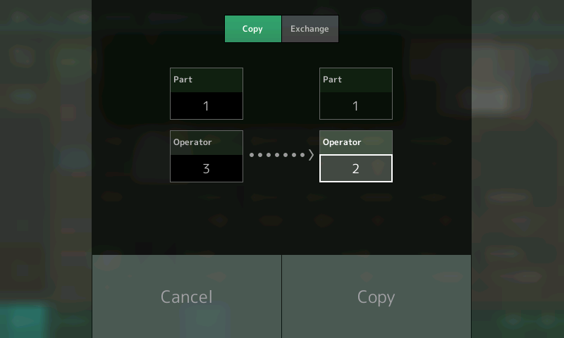
- Touch Copy to complete the procedure. To confirm that the envelope settings for Operator 2 have been reverted back to the default settings (as a result of being copied from Operator 3), touch the OP2 tab at the bottom of the screen:

- Now all that remains to be done is to change the Release Time of Operator 2 to 65 (so we can hear the full effect of the Operator 1 EG fading away after we let go of a key) and to restore Operator 2’s Level to 99. (Remember, all the data from Operator 3—including its Level, which was still at its default value of 0 since it never got changed—was copied to Operator 2 … and we won’t hear anything at all if Operator 2’s level is at 0, since it’s the carrier in this algorithm.) This would be a good time to save the sound, calling it “Part 4_02”. (Click here to download it from Soundmondo.)
- Play a note on the keyboard and hold it for ten seconds or so, then let go of the key, listening carefully as you do so. This is what you’ll hear:
Clearly, the EG’s “invisible hand” is turning the level of the modulator up and down, causing timbral sweeps as the initial sine wave quickly develops more overtones during the Attack portion before slowly transforming into a less complex sound during the Decay1 portion. After a few seconds the sound jumps in timbral complexity again (the Decay2 portion) and remains that way as long as you hold the key. When you let go of the key, the Release portion kicks in, and all the overtones start disappearing until the sound ends up as just a simple sine wave again. (Note: Setting a modulator’s Release/Hold value the same as its Decay2 value is a great way of creating a sound that has no timbral change whatsoever when you let go of any keys you’re holding down.)
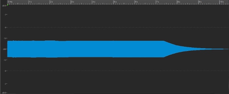
However, one big difference between this waveform and the one for the sound we previously created is that there is no change in amplitude throughout the duration of the sound, as you can easily see:
Obviously, you can do a lot more experimentation with EGs. For example, try copying the same envelope from Operator 1 (the modulator) into Operator 2 (the carrier), then save the Performance as “Part 4_03.” (Click here to download this performance from Soundmondo.) If you hold down a note on the keyboard for ten seconds or so, you’ll hear the same timbral change, but this time occurring in sync with the volume change: as the sound gets more complex, so too does it get louder, and vice-versa—the fewer the overtones, the softer the sound. Here’s an audio clip that demonstrates what you’ll hear:
Once you’ve got the dynamics of this modulator/carrier “system” tweaked to where you like it, consider altering the Frequency Ratio of one or both operators (perhaps setting up a non-integer relationship for the generation of some inharmonic overtones, or adding some detuning or feedback—digital FM functions that were all described in Part 3).
Speaking of Part 3, now that we understand how envelopes work, this would be a good time to go back and tweak a couple of the sounds created in the exercises presented in that article. For example, we can get the clarinet-ish sound of the “Part 3_05” Performance (click here to download it from Soundmondo) sounding a lot more like a real clarinet. Here’s how:
- Change the EG Times for Operator 2 (the carrier) as follows:
- Hold = 0; Attack = 33; Decay1 = 0; Decay2 = 0; Release = 40
- We’ll use the envelope of the modulator (Operator 1) to simulate the extra degree of timbral complexity that occurs at the beginning of most musical sounds, as described earlier in this article. Accordingly, enter the following Times and Levels into the Operator 1 EG:
- Times: Hold = 0; Attack = 0; Decay1 = 25; Decay2 = 32; Release = 30
- Levels: Attack = 99; Decay1 = 50; Decay2 = 91; Release/Hold = 0
- Finally, change the Level of Operator 1 to 76 and change the Feedback value to 7 (to further increasing the degree of timbral complexity at the start of the sound), then save the Performance as “Part 4_04.” (Click here to find this Performance on Soundmondo)
Here’s what it sounds like:
- And here’s how to turn the percussive “Part 3_07” Performance (click here to download it from Soundmondo) into realistic-sounding bells:
- Start by increasing the Release time for Operator 2 (the carrier) to a value of 63 so that the sound rings out after releasing a key.
- Then set the Release time for Operator 1 (the modulator) to a slightly faster value of 60 so that the sound audibly changes to a simple sine wave just as it fades out.
- Next, set Operator 1’s Decay2 level to a value of 58 and change its overall Level to 75.
- Finally, change the Feedback value to 7 to maximize the number of inharmonic overtones generated, and save the Performance as “Part 4_05.” (Click here to find this Performance on Soundmondo)
Here’s what it sounds like:
As you can see (and hear), the role of operator envelope generators comes down to these two simple rules:
FM RULE 4: Carrier EGs cause amplitude to change over time … and nothing else about the sound.
FM RULE 5: Modulator EGs cause timbre to change over time … and nothing else about the sound.
But, as we learned earlier in this article, sounds sometimes also change in frequency (pitch) throughout their duration, though if this does occur it is usually much more subtle than amplitude or timbral change. In digital FM synths, this is the function of a component called …
The Pitch EG
The only major difference between the Pitch EG and other envelope generators is that it always affects the overall sound, so if you’re creating a digital FM sound, it affects all operators simultaneously, not individual operators. For that reason, it’s accessed from the Common edit screen. Here’s how to get there:
- Press [PERFORMANCE]
- Press [EDIT]
- Press [PART SELECT 1/1]
- Touch the Pitch/Filter tab on the far left-hand side of the screen
- Touch the PEG/Scale tab on the left-hand side of the screen
- The resulting screen, shown in the illustration below, displays the PEG shape and controls (circled in red):
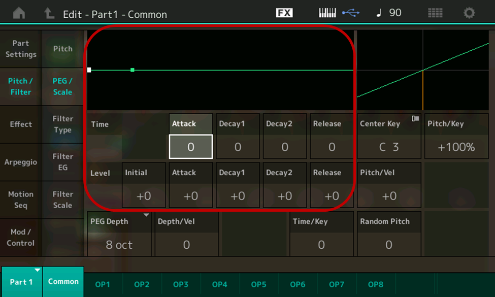
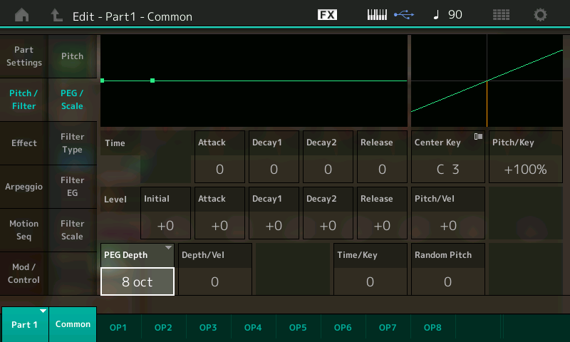
As you can see, the controls are somewhat similar to those of operator envelopes. However, there are four times and five levels, as opposed to the five times and four levels offered by operator EGs. Though there is no Hold time, the Attack, Decay1, Decay2 and Release times offer the same 0 – 99 range (with 0 being the fastest time and 99 the slowest) as operator envelopes. However, the Attack, Decay1, Decay2 and Release levels offer both positive and negative values (from +50 to -50) so that the pitch can go either sharp or flat. Note that there is also an Initial Level, which allows the Pitch EG to start on a different frequency. This enables you to slur into a note, similar to the technique used by guitarists when they bend a string. There’s also a PEG Depth parameter (highlighted in the illustration below) that allows you to “fine-tune” the overall range of the pitch envelope, from 8 octaves (the coarsest setting) to 0.5 octaves (the finest setting). The lower this value, the more subtle the effect of the PEG.
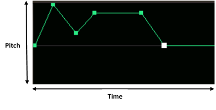
The Pitch EG works in a similar way to operator envelopes: When a Note On signal is generated by virtue of you playing a note on your synth’s keyboard (or via an incoming MIDI signal), the Pitch EG begins its journey to whatever Attack Level you’ve set, at a rate determined by the Attack Time you’ve set. Once it arrives at the Attack Level, it continues on to the Decay1 Level, at a rate determined by the Decay1 Time. From there, it continues onto the Decay2 Level, at a rate determined by the Decay2 Time. It then remains at the Decay2 Level until you let go of the key, at which time a Note Off signal is generated and the Pitch EG begins its final journey, on to the Release Level, at a rate determined by the Release Rate. (Unlike operator EGs, the Release Level does not do double duty as a Hold Level, since it cannot end on a different frequency than its starting pitch.)
By the way, in case you’re wondering why you haven’t been hearing the Pitch EG up until now, the answer lies in the default settings shown in the previous two illustrations. Since all five levels are set to +0, there is no change in pitch. Of course, these values (and the times it takes for the PEG to travel between them) can easily be changed. Let’s run some exercises to discover some of the ways the Pitch EG can affect a sound.
- Start by loading the “Part 4_04” Performance created earlier, or download it from Soundmondo)
- Press [PERFORMANCE]
- Press [EDIT]
- Press [PART SELECT 1/1]
- Touch the Pitch/Filter tab on the far left-hand side of the screen
- Touch the PEG/Scale tab on the left-hand side of the screen
- Enter the following values to fashion a Pitch EG shape similar to the operator envelope shape we recreated earlier:
- Times: Attack = 40; Decay1 = 50; Decay2 = 40; Release = 50
- Levels: Initial = +0; Attack = +50; Decay1 = +15; Decay2 = +40; Release = +0
- Save this Performance as “Part 4_06.” (Click here to find this Performance on SoundMondo)
The resulting Pitch EG shape looks like this:
And if you play a note on the keyboard, it sounds like this:
As mentioned previously, Pitch EG Levels can be set to either positive or negative values, enabling the pitch to go either sharp or flat. To hear what this sounds like, change the Attack, Decay1 and Decay2 Levels for this newly constructed Pitch EG to their negative equivalents (Attack = -50; Decay1 = -15; Decay2 = -40). The Pitch EG now looks like this:
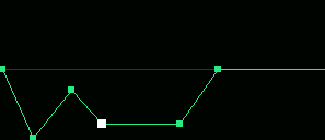
And this is what you’ll hear if you play a note on the keyboard:
Obviously, drastic pitch changes like these aren’t particularly useful unless you’re looking to create a sound effect—that’s because, as noted earlier, any change to the frequency of most sounds is usually quite subtle. With that in mind, let’s devise a more practical use for the Pitch EG:
- Load the “Part 4_04” Performance created earlier, or download it from Soundmondo.
- Change the Pitch EG Attack Time to 50 and the Initial Level to -4. The resulting Pitch EG shape looks like this:
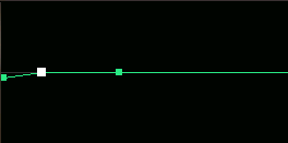
- Play a few notes on the keyboard. This is what you’ll hear:
Even though all we did was tweak two Pitch EG parameters in order to have the note start a little flat before gently slurring up to pitch, this has changed the sound pretty dramatically, from being clarinet-ish to something that’s more akin to a harmonica or reed organ—a great demonstration of the way that even subtle changes in digital FM have a dramatic impact on the sound. For future reference (and as a great reminder of this principle), be sure to save this Performance as “Part 4_07” before moving on. (Click here to find this Performance on Soundmondo.)
In addition to allowing you to construct complex shapes by entering Time and Release values, all envelopes (including the Pitch EG) provide the ability to “follow” the range of keys you’re playing. In modern instruments like MONTAGE and MODX, this feature is called …
Time/Key
This function allows you to construct sounds that vary in complexity as you go up and down the keyboard by setting the degree to which the notes you play (specifically, their position or octave range) affect the EG or PEG Times. This is particularly important when you’re looking to simulate the sounds of musical instruments, since notes of higher pitch tend to undergo amplitude, timbral and pitch change more rapidly than notes of lower pitch. That’s one of the reasons why, in almost all musical instruments, high notes sound more shrill to our ears than low notes: not only are the overtones higher (because they are multiples of a higher fundamental), but they are undergoing change more rapidly.
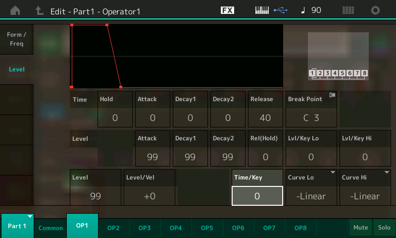
Each operator envelope display offers its own independent Time/Key parameter (highlighted in the illustration below):
And there’s a single Time/Key parameter (highlighted below) in the Pitch EG display as well:
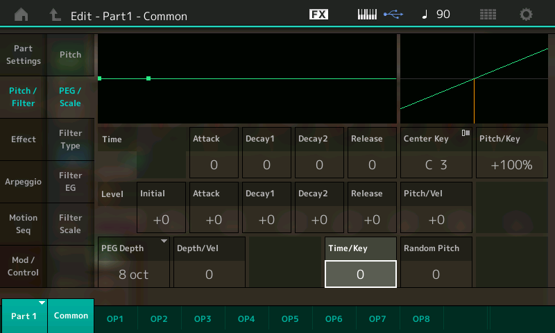
Like all other controls that have to do with output level, Time/Key affects amplitude change (if the operator is a carrier) or timbral change (if the operator is a modulator); in the Pitch EG, it affects pitch change (for all operators). The range of values you can enter goes from 0 – 7, with 0 indicating that regardless of the notes you are playing, the EG/PEG times stay the same; with higher values, the degree of change increases.
As usual, this is easier to hear than it is to describe, so let’s start by altering the Time/Key parameter in operator envelopes.
- Load the “Part 4_03” Performance created earlier, or download it from Soundmondo.
- This Performance has the same EG Time and Level values for both the carrier (Operator 2) and modulator (Operator 1) envelopes, causing identical amplitude and timbral changes, with shapes that look like this:

- Start by changing the Time/Key parameter for both Operators 1 and 2 to a value of 7, then save the Performance as “Part 4_08.” (Click here to find this Performance on Soundmondo.)
- Play a few notes, holding each key down for ten seconds or so. You’ll hear the amplitude and timbral change speed up as you play higher notes, and slow down as you play lower notes. Try playing an octave—say, middle C along with the C an octave higher—and hold down both keys for ten seconds. You’ll hear the note an octave higher complete its EG journey exactly twice as fast as the note an octave lower:
- Now play both Middle C and the C an octave lower and hold down both keys. You’ll hear the C an octave lower take exactly twice as long to complete its EG journey as Middle C.
- Set the Time/Key parameter in Operator 2 (the carrier) to 0, then play a few notes on the keyboard, holding each down for ten seconds or longer. You’ll hear the timbral change occur more rapidly as you play higher notes, while the amplitude change is the same regardless of the note you play. Then do the reverse: restore the Time/Key parameter for Operator 2 back to a value of 7, but set it in Operator 1 to a value of 0. This time, if you play a few notes on the keyboard, holding each down for ten seconds or longer, you’ll hear the amplitude change occur more rapidly as you play higher notes, while the timbral change is the same regardless of the note you play.
- Finally, change the Time/Key parameter for Operators 1 and Operator 2 to lesser values, then play some notes on the keyboard, holding them down for several seconds. You’ll find that playing higher notes still causes the amplitude and/or timbre to change somewhat more rapidly, but that there’s less difference as you go from note to note.
Now let’s take a look at how Time/Key works for the Pitch EG.
- Load the “Part 4_06” Performance created earlier, or download it from Soundmondo.
- In this Performance, we changed several Pitch EG values to create an audible “swoop” up in pitch along with a double attack of both amplitude and timbral change. Go to the Pitch EG display and change the PEG Time/Key parameter to a value of 7, then save the Performance as “Part 4_09.” (Click here to find this Performance on Soundmondo.)
- Play a few notes on the keyboard, holding each down for ten seconds or longer. You’ll hear the pitch change occur more rapidly as you play higher notes, while the amplitude and timbral change remains the same regardless of the note you play.
- Play middle C along with the C an octave higher, and hold down both keys for ten seconds. You’ll hear the C an octave higher complete its pitch change considerably faster. (Due to complex mathematical relationships outside of the scope of this article, it won’t, however, be exactly twice as fast.)
In summary, envelopes allow you to create sounds that change in amplitude, timbre and pitch throughout their duration … just like all naturally occurring sounds. But there are two other means of adding dynamics and real-time expressivity to your digital FM sounds, the same way musicians do when playing acoustic musical instruments.
Real-Time Control: Velocity Sensitivity and Physical Controllers
Since the early 1980s, velocity sensitivity (which, by the way, was an integral part of the original Yamaha DX7) has become a mainstay of pretty much all synthesizers, and many other electronic musical instruments as well—even those that don’t have keyboards. What many people don’t realize, however, is that velocity is actually a time measurement. A keyboard instrument, for example, will be clocking how quickly a key moves from its resting position to being depressed. Obviously, the harder you strike a key, the faster it drops down, while the softer you strike it, the longer it will take to move from its resting position. The instrument’s internal clock simply counts the number of “ticks” between the instant a key starts to move and the instant it reaches the bottom of its movement. And since these clocks are running very quickly (millions of times per second in modern synths), they are very accurate in presenting that information to the internal microprocessor. The question is, what does the microprocessor do with that information?
Well, one of its main uses in digital FM is to apply this so-called “key velocity” value to the output of individual operators. As we’ve learned, altering the output of a carrier results in a change in amplitude, while altering the output of a modulator results in a timbral change. So this usage of a velocity sensitivity means that the harder you strike a key, the louder and/or more timbrally complex the resulting sound. This is of tremendous value since it’s precisely the way virtually all musical instruments work: The harder you hit a piano key (or pluck a guitar string, or blow into a wind instrument, or strike a percussion instrument) the louder and more timbrally complex the sound. Conversely, the more gently you strike the key / pluck the string / blow into the wind instrument / hit the drum, bell or cymbal, the softer and timbrally less complex the sound.
In modern digital FM instruments like MONTAGE/MODX, velocity sensitivity is set by altering a “Level/Vel” parameter in each operator’s envelope display, as highlighted in the illustration below.
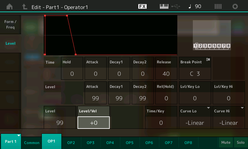
Level/Vel can be set to both positive or negative values, from -7 to +7, where increasing positive values result in more sensitivity, so that the harder you strike a key, the greater the effect of the EG on output level; with decreasing negative values, the harder you strike a key, the less the effect of the EG on output level. (A value of +0, which is the default that’s been used in all our exercises up until now, means that the EG and resultant output level is unaffected by how hard or soft you strike a key.) Take some time to experiment with any of the digital FM sounds we’ve created in these articles to get familiar with the way velocity sensitivity can be used to affect volume and/or timbre as you play.
The Pitch EG has a similar “Depth/Vel” parameter (highlighted in the illustration below) that enables you to link the degree of pitch change made by the PEG to the force with which you strike a key.
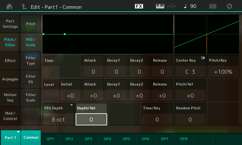
Unlike operator Level/Vel, the Pitch EG Depth/Vel parameter can only be set to positive values (from 0 to 7); increasing values result in greater sensitivity so that the harder you strike a key, the more you hear the effect of the Pitch EG. (A value of 0, which is the default that we’ve been using up until now, means that the pitch change is unaffected by how hard or soft you strike a key.) Again, take some time to experiment with any of the digital FM sounds we’ve created to get familiar with the way velocity sensitivity can be used to create pitch change as you play.
Here’s an exercise that shows how to use velocity sensitivity to impart amplitude, timbral and pitch change in varying degrees, all at the same time:
- Call up the “Part 4_05” Performance created earlier. (Click here to find this Performance on Soundmondo.) You may recall that this was a modification of the percussive “Part 3_07” Performance that transformed it into a bell-like sound.
- Change the Lev/Vel of Operator 2 (the carrier) to a value of +2
- Change the Lev/Vel of Operator 1 (the modulator) to a value of +7
- Go to the Pitch EG display and enter the following data:
- Change the PEG Depth to 0.5 oct
- Change the Release Level to -30
- Change the Release Time to 99
- Save the Performance as “Part 4_10.” (Click here to find this Performance on Soundmondo.)
- Play a few notes, striking the keys at varying levels of intensity. Note that the harder you play a key, the louder the sound and the greater the timbral complexity … and if you strike a key really hard, you’ll hear the pitch drop off about a semitone as it fades away. (Bonus: Play a key several times with varying degrees of strength and you get a cool chorusing effect!) Applied to bell-like sound such as this, the effect is downright spooky! Here’s what it sounds like:
(Note: The Pitch EG display screen offers another parameter [located to the right of the Release Level parameter] related to velocity sensitivity. This is called Pitch/Vel, short for “pitch velocity.” However, despite being located in the PEG screen, this parameter is not related to the PEG; instead, it determines how the overall pitch of a sound responds to velocity, over a range of -64 to +63. When positive values are entered here, the harder you play the keyboard, the more the pitch rises; with negative value, the harder you play the keyboard, the more the pitch falls. With the default value of +0, there is no change in pitch.)
As mentioned previously, just as envelopes are used to create an aperiodic (once only) change in sound, LFOs (Low Frequency Oscillators) are used to create a periodic, repeating change in sound. In all synths, the LFO speed can be set by the user, and there’s usually the ability to select from several preset waveform shapes; there are also generally numerous options for routing LFO signal through real-time controllers such as modulation wheels or ribbons (see below). In digital FM synths specifically, the output of the LFO can be routed to either the pitch or amp inputs of any or all operators; the user can generally also set the degree to which each operator is affected (in modern FM-X synths such as MONTAGE and MODX, this is called “Operator Depth Ratio”). At first glance, it may seem that routing an LFO signal to operator pitch inputs will result in a periodic change in frequency (i.e., vibrato), but that’s only the case if you route it to the pitch inputs of all operators, because routing it to just some operator pitch inputs may result in a timbral change instead, since you may be upsetting the frequency ratio between modulators and carriers. However, routing LFO signal to carrier amps always causes a change in amplitude (resulting in a tremolo effect), while routing it to modulator amps always results in a timbral change.
Last but by no means least in the toolbox of ways to create dynamic FM sounds is the use of physical controllers to alter sonic components in real time. These include keyboard aftertouch (where the amount of pressure applied to a key after it is depressed is used to alter an aspect of the sound) as well as built-in devices such as pitch bend and modulation wheels, ribbons, assignable knobs and switches, and (in the case of MONTAGE and MODX) a “Super Knob” that can control multiple parameters in just about every way imaginable, plus a Motion Control feature that can use rhythmic sources such as arpeggios, drum patterns, and the changing amplitude of external audio to modulate FM operators. Plus there are a gamut of readily available external control devices that can be plugged into your digital FM instrument, such as footpedals and switches, breath controllers, and incoming MIDI “control change” messages being generated by other synths, hardware sequencers and computer software such as DAWs. In MONTAGE and MODX, you can use any or all of these to alter a vast array of parameters in real time, including individual operator output levels, frequencies, detuning and EG times, as well as feedback amount and Pitch EG attack and release times. Between envelopes and real-time controllers, the options for adding dynamics and expressivity to the digital FM sounds you craft are nearly unlimited!
We’ve come a long way in our understanding of the basic principles of digital FM, but up until now all our explorations have been limited to a single two-operator “system” consisting of one carrier and one modulator. In Part 5, we’ll expand our palette by building sounds from multiple operators and learn how to selectively spread individual sonic components across the keyboard. Until then, happy programming!
Missed any part of this series? Click on the links below:
FM 101, Part One: Discovering Digital FM…John Chowning Remembers
FM 101, Part Two: The Basics
FM 101, Part Three: The Magic of Modulation
Tagged Under
Keep Reading
Keep Reading
© 2025 Yamaha Corporation of America and Yamaha Corporation. All rights reserved. Terms of Use | Privacy Policy | Contact Us


