We take your Privacy very seriously.
Part III
In Part 2 of this series, we discussed basic audio theory and focused on the building block of digital FM synthesis: the operator. We also learned that an operator we can hear is called a carrier. But sometimes the output signal coming from an operator is not routed to your instrument’s output or headphone jacks, but is instead routed to the input of another operator, like this:
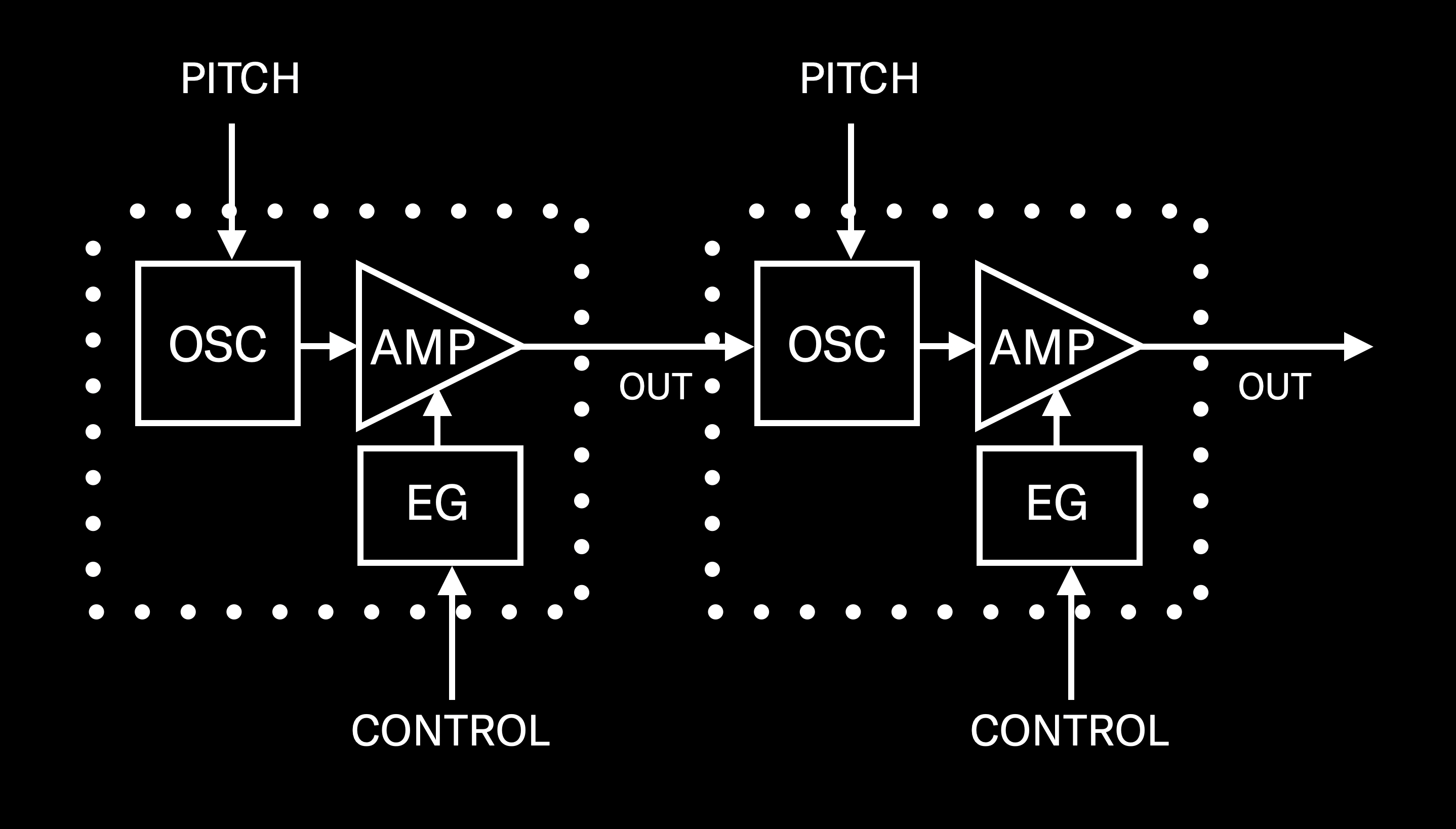
These kinds of operators are called modulators, and they cannot be heard. Instead, we hear their influence on the operator (or, in some cases, operators) they are affecting, or modulating. Other than that, there is absolutely no difference between a carrier and a modulator—they have precisely the same internal software components: an oscillator, an amplifier, and an envelope generator.
As stated in Part 2, digital FM synthesizers always offer multiple operators. In the case of modern instruments like the MONTAGE and MODX, there are eight of them, all functionally identical, labeled OP1, OP2, OP3, etc. (Even early FM instruments like the original Yamaha DX7 offered six operators.) So how do we know which operators are acting as carriers, and which as modulators? The answer lies in the algorithm being used.
“Algorithm” is a word that tends to strike fear in the hearts of newcomers to digital FM, but it’s actually just a simple computer term that means “a set of instructions designed to carry out a particular task.” For example, if you instruct a computer (in code) to add together two numbers, that’s an algorithm, albeit a very simple one. If you instruct it to put up a picture of the Mona Lisa on your screen and display it in 12,000 different shades of purple, that’s also an algorithm—albeit a much more complex (and much more useless) one.
We’ll be discussing algorithms in much greater detail in Part 5 of this series, but for now you really only need to know a couple of basic facts about them:
- Modern FM instruments like MONTAGE and MODX offer 88 different algorithms. (The original DX7 had 32 of them.) You can view them in the online Data Lists for your instrument, or onscreen—we’ll show you how to do the latter shortly.
- Yes, they may appear as hieroglyphics at first, but deciphering these images is actually easy: Operators on the bottom row are carriers, while those above them are modulators, and there are lines that indicate where the output signals of those modulators are routed.
Up until now, we’ve only been working with Algorithm 1. That’s because this is the default algorithm when you select an initialized Performance such as “Init Normal (FM-X),” which has served as the template for all the exercises we’ve been doing thus far.
Here’s what Algorithm 1 looks like:

As you can see, all eight operators are on the bottom row, meaning that in this algorithm, they all serve as carriers. (Sharp-eyed observers will also notice a line around Operator 1; this is called a feedback loop, and is something we’ll also be discussing in detail shortly.)
Since this installment is all about modulators and modulation, this algorithm isn’t going to be of much use to us. Instead, for the purposes of this article, we’ll be working with Algorithm 67, which looks like this:

In this algorithm, the odd-numbered operators (1, 3, 5 and 7) are all sitting above the even-numbered operators (2, 4, 6 and 8), with lines indicating that Operator 1 is sending its output signal into Operator 2, Operator 3 into Operator 4, Operator 5 into Operator 6, and Operator 7 into Operator 8. (Operator 1 also has a feedback loop.) In other words, the odd-numbered operators are acting as modulators, and the even-numbered operators below them are the carriers they are modulating.
Armed with this basic information, we’re ready to take a closer look now at …
Modulator/Carrier Interaction
Of course, the best way to understand this is to hear it. Accordingly, in your MONTAGE or MODX, call up the “Part 2_01” Performance you created in Part 2 of this series, or click here to download it from the Soundmondo website. (This is simply “Init Normal (FM-X),” saved without reverb.)
Play a few notes. You’ll hear a sine wave. Which operator are we hearing? To find out, do the following:
- Press [EDIT]
- Press [PART SELECT 1/1]
- Touch the OP1 tab at the bottom of the screen or press the [MOTION SEQ SELECT 1] button (this button calls up Operator 1 when working with an FM-X part)
- Touch the Level tab on the left-hand side of the screen to bring up the OP1 level screen, then view the Level box on the bottom row (circled in red):
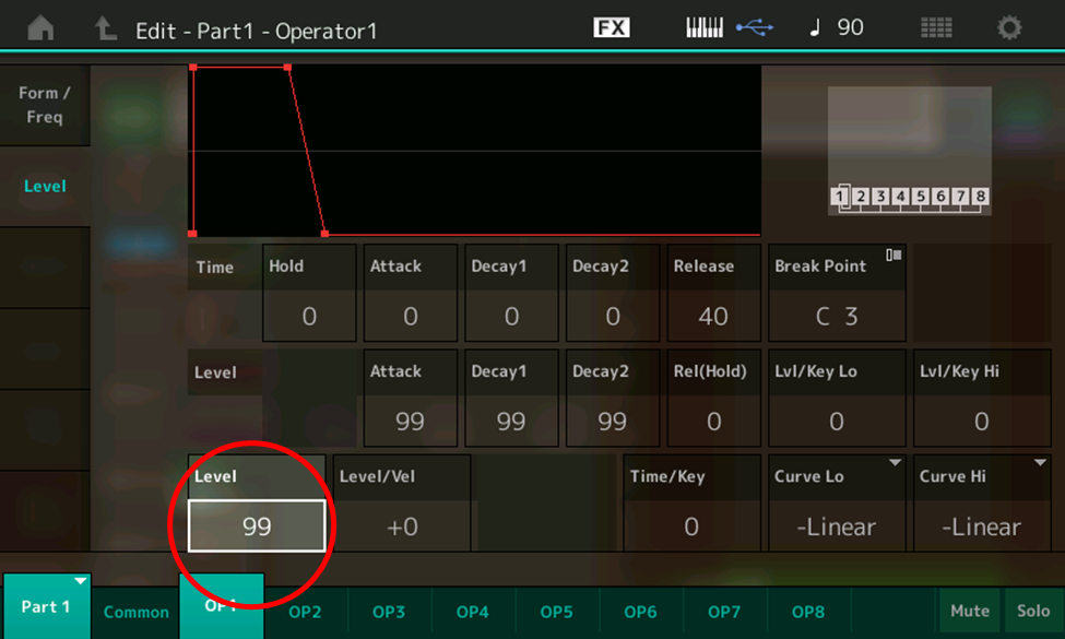
- Note that the level of OP1 is currently set at 99 (maximum). Now, one at a time, touch the OP2 – OP 8 tabs at the bottom of the screen. Note that their levels are all set to 0. Clearly, we are only hearing Operator 1.
- Touch the Common tab at the bottom of the screen, then touch the Algorithm tab on the left-hand side of the screen (circled in red):
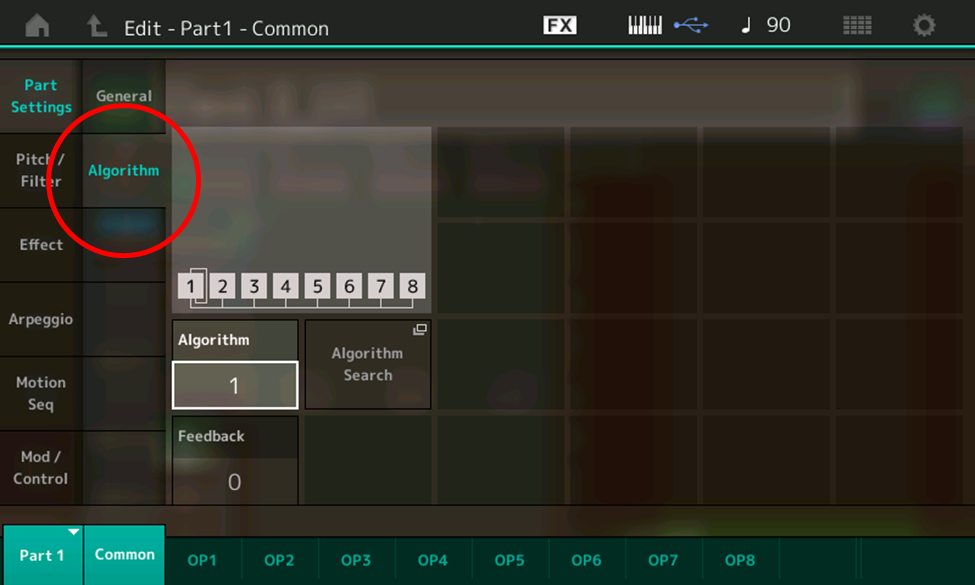
- With the Algorithm data box highlighted (as shown in the illustration above), use the INC/YES button or data dial to scroll through all 88 algorithms. This allows you to view their configurations onscreen. When you’re done, touch the Algorithm data box to get an onscreen numeric keypad display:
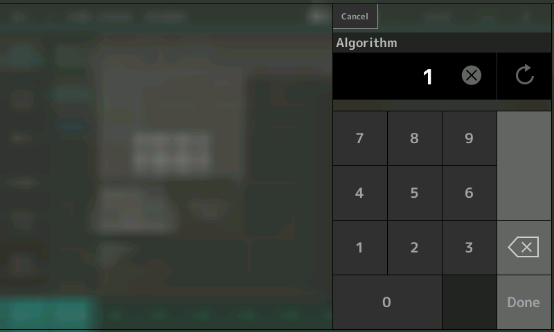
- Enter 67, then press Done to return to the Edit – Part 1 – Common – Algorithm screen, this time with Algorithm 67 selected:
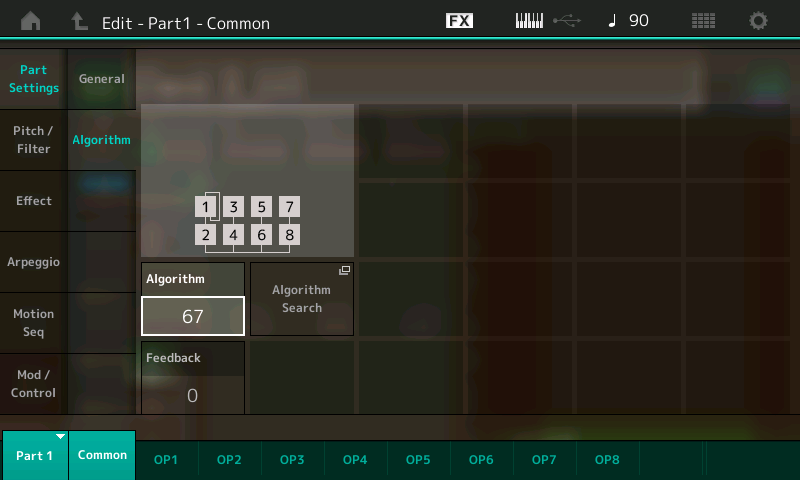
- Play a few notes on the keyboard. This time you’ll hear … nothing. That’s because, in Algorithm 67, Operator 1 (which is the only operator with a level other than 0) is acting as a modulator, not a carrier. Remember, the only operators you can ever hear are carriers. You can’t hear modulators. However, you will hear their influence on any carriers they are modulating.
We’ll spend much of the rest of this article exploring the effect that a modulator has on a carrier, but for now, set Operator 1’s level to 0 and the level of Operator 2 (a carrier in this algorithm) to 99, following the steps outlined above, then save the Performance as “Part 3_01.” (You can also find this Performance on the Soundmondo website by clicking here.)
First, though, let’s discover the answer to this basic question …
What Is FM?
FM is an acronym for “Frequency Modulation,” and it’s something that existed long before there were computers or digital synthesizers. For more than 70 years, it’s been widely used for radio transmission when applied to waves with rates of millions of cycles per second (as opposed to the 20 to 20,000 cycle-per-second range that we can hear—see Part 2 for more information.) But for much longer than that—millennia, in fact—it’s been an integral part of music, where it’s used to create vibrato.
Vibrato is a subtle, pulsating change of pitch—a form of musical expression that every trained singer and most instrumentalists regularly apply, typically to held notes, by moving their larynx, finger or hand. (Pianists, alas, and some percussionists don’t have any means of adding vibrato due to the construction of their instruments, but most every other musician can do so.) And it was a fascination with vibrato and how it affected spatialization (the ability to move a sound source in a three-dimensional field, and the way the human ear distinguishes those movements) that led to Stanford professor Dr. John Chowning’s discovery of digital FM, as described in Part 1 of this series.
“I was searching for sounds that had some internal dynamism,” he explains, “because for localization one has to have sounds that are dynamic in order to perceive their distance. The direct signal and the reverberant signal have to have some phase differences in order for us to perceive that there are in fact two different signals. Vibrato is one of the ways that one can do that.”
As related in Part 1, Chowning’s “ear discovery,” as he called it, occurred one evening in 1967 as he was using Stanford’s mainframe computer to digitally model the sound of two sine wave oscillators in a simple modulation configuration, one slowly altering the pitch of the other to produce vibrato. Curious as to what would occur if he increased the rate and/or depth beyond what was possible with the human touch, he issued instructions to the computer to double and triple some of the numbers. And that’s when a curious thing happened: At the point when the rate of the vibrato increased to where it could no longer be perceived as a cyclical change, the sound changed from simple pitch fluctuation into a timbral change—a change in tonality. What’s more, as the rate and depth increased further, he heard more and more timbral complexity.
From Vibrato to Timbral Complexity
Ready to replicate what happened that fateful evening? Fire up your MONTAGE or MODX, call up the “Part 3_01” Performance you created earlier (or download it from Soundmondo) and let’s make it happen!
- Press [EDIT]
- Press [PART SELECT 1/1]
- Touch the OP1 tab at the bottom of the screen or press the [MOTION SEQ SELECT 1] button
- Touch the Form/Freq tab in the upper left-hand corner of the screen and in the FreqMode box, select Fixed (circled in red in the illustration below):
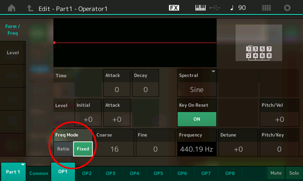
- This is not a mode we’ve used before—all of our experimentations in Part 2 were in Ratio mode—but it’s not complicated. When “Fixed” is selected, instead of following what you play the keyboard, the oscillator in the operator in question simply outputs its sine wave at whatever frequency you set in the Coarse and Fine boxes. The default, as shown in the illustration above, is a Coarse value of 16 and a Fine value of 0, which results in a fixed frequency of 440.19 Hz—pretty close to an A440. Experiment with touching the Coarse and Fine boxes and changing their values in order to see the various frequencies that are available. When you’re done experimenting, set the Coarse value to 7, and the Fine value to 28. As you can see in the Frequency box, this will cause the oscillator in Operator 1 (the currently selected operate) to output its signal at a frequency of 1.0005 Hz, or roughly one cycle per second.
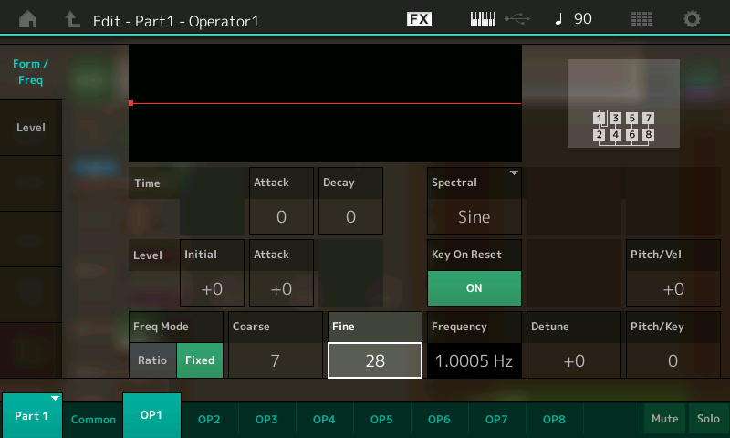
- This would be a good time to save the Performance as “Part 3_02” (you can also click here to download this Performance from Soundmondo).
- Now it’s time to raise the level of Operator 1 (in this case, the modulator) so you can hear its effect on Operator 2 (in this case, the carrier). The easiest way to do this is to simply move the first Control Slider on the left-hand side of your instrument. (As we discussed in Part 2, whenever you are working with an FM-X Part, these sliders are preset to control the levels of Operators 1 – 8 respectively.) Tip: You can activate the Control Sliders even if your MONTAGE or MODX is not in Edit mode—simply press the appropriate PART SELECT button (in this case, [PART SELECT 1/1]). You’ll be shown the following screen:
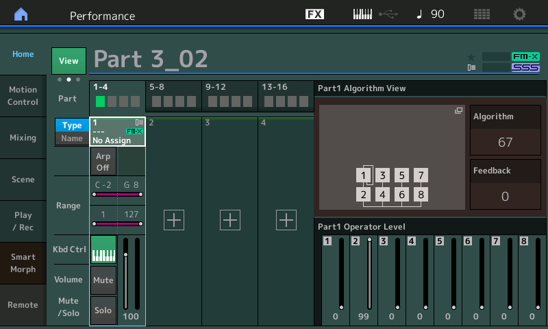
- Slowly raise Control Slider 1 as you hold down a note or chord on the keyboard and listen closely; at first, there’s little change, but as you get close to maximum level (99), you’ll hear the pitch begin wobbling back and forth, at a rate of approximately—you guessed it!—once per second. Now play some different notes and chords. Note that this rate of speed is the same for all notes (although it will start at different points in the cycle if you play arpeggiated chords). That’s because, when Fixed Frequency Mode is selected, the oscillator in the operator is not receiving any pitch data from the keyboard—in the vernacular, it’s not “tracking” the keyboard.
- Leave the level of Operator 1 at maximum (99) and touch the Fine box, then use the INC/YES button or data dial to slowly raise the frequency from 1.0005 Hz to its maximum (when the Fine value is set to 127) of 1.7102 Hz, holding down a note or chord on the keyboard and listening as you do so. Note that the wobble increases in speed as you do so.
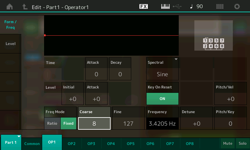
- Leaving the Fine control at 127, touch the Coarse box and press the INC/YES button to increase its value from 7 to 8, listening as you do so. Note that the rate of vibrato doubles, as is confirmed by the Frequency box now displaying 3.4205 Hz:
- Keep pressing the INC/YES button to increase the Coarse value as you continue holding down a note or chord on the keyboard. Note that the rate of vibrato doubles each time you do so. With a Coarse value of 9 (6.8409 Hz), a very musical vibrato is quite apparent. But when you take it up a notch, to Coarse values of 10 (13.681 Hz) or 11 (27.363 Hz), it’s a lot harder to hear clearly as a vibrato, as these audio clips demonstrate:
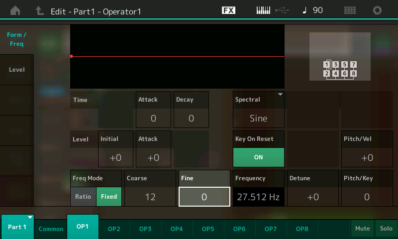
- Here’s where the magic starts to happen, because as you may recall (we discussed this in Part 2), 20 Hz is roughly the low end of the audible range—the range of frequencies that we humans can hear. If you set the Coarse value to 12 and the Fine value to 0, the modulator will output a frequency of 27.512 Hz, as shown in the screen:
- Set the level of Operator 1 to 99 by touching the Level tab on the left-hand side of the screen, selecting the Level box, and then using the INC/YES button or data dial (or, if you’re not already in Edit mode, by pressing [PART SELECT 1/1] and then moving the first Control Slider on the left-hand side of your instrument). Then save the Performance, this time calling it “Part 3_03” (you can click here to download this Performance from Soundmondo).
- Touch the Fine box, and, while holding a note down on the keyboard, use the INC/YES button or data dial to slowly raise the value from 0 to 127 (54.727 Hz). What you’ll hear is a clear and obvious shift from a very fast vibrato to a timbral change in the sound, caused by the addition of overtones—both harmonic and inharmonic—to the basic sine wave being output by the carrier (in this case, Operator 2). This was Chowning’s eureka moment! Here’s what it sounds like:
- Continue experimenting by changing the Coarse and Fine values for Operator 1, holding down a note or note and listening to various timbral shifts that occur. Some values result in musical tones, while others result in clangorous tones resembling bells and chimes. We’ll explain the reason why very shortly.
Vibrato is defined by two factors: its speed and its intensity. In the case of digital FM, we can see (and hear) clearly that its speed is determined by the frequency of the modulator. But what determines its intensity? The answer is simple: the output level of the modulator.
This is a key concept to understanding how digital FM works: Carrier output level determines how loud the sound will be, while modulator output level determines how timbrally complex the sound will be. In other words, the higher the modulator output level, the more overtones are generated. Let’s run a simple exercise to demonstrate this:
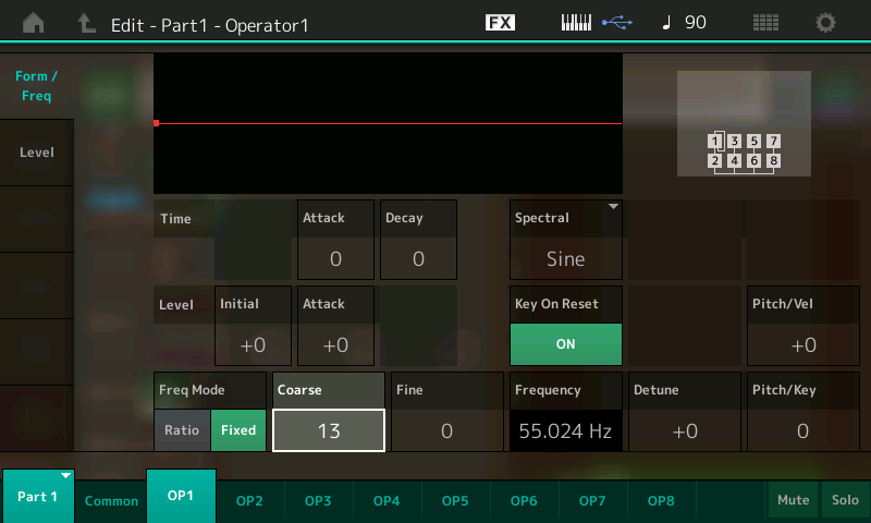
- Call up the “Part 3_03” Performance you saved (or download it from Soundmondo) and change Operator 1’s Coarse value to 13, for a frequency of 55.024 Hz, as shown in the illustration below:
- Save this Performance as “Part 3_04” (or download it from Soundmondo).
- Slowly raise the level of Operator 1 as you hold down a note or chord on the keyboard, listening carefully as you do so. This can be accomplished by touching the Level tab on the left-hand side of the screen, selecting the Level box, and then using the INC/YES button or data dial (or, if you’re not already in Edit mode, by pressing [PART SELECT 1/1] and then moving the first Control Slider on the left-hand side of your instrument). This is what you’ll hear:
At first, there isn’t much change, but when the level of Operator reaches a value of 65 and higher, the sound becomes buzzier and buzzier. That’s because more and more overtones are being generated as the amount of modulation increases.
Ratio Modulation
So far, all of our experiments in this article have been conducted with the modulator in Fixed Frequency mode—in other words, without it receiving pitch input from the keyboard (or a connected MIDI source). But, as we saw in Part 2, operators that are set to Ratio mode “track” the keyboard—in fact, that’s the way they work in most digital FM sounds. And, as we learned, the Ratio value you enter is used as a multiplier, so that, for example, if you set it to 1.00 and you play A above middle C, the operator multiples 440 (that note’s frequency) by 1.00, resulting in an output of 440 Hz (440 times 1). If, on the other hand, you set the Ratio to 2.00 and play A above middle C, the frequency of the operator’s output will be 880 Hz. We also discussed the fact that a Fine control allows you to also enter fractional Ratio values, so that if an operator’s Ratio is set to 1.5 and you play A above middle C, for example, its output will have a frequency of 660 Hz (440 times 1.5).
In a modulator/carrier configuration, this means that both the source of the modulation (the modulator) and the source of the audio signal (the carrier) are changing frequency as you play different notes on the keyboard. This enables you to craft complex timbres that do not change regardless of the note you play (very important!) and also allows you to predict, with complete mathematical certainty, the kind of timbre you create (even more important!).
As with other aspects of digital FM, this concept is easier to hear than explain, so call up the “Part 3_01” Performance you created earlier (or download it from Soundmondo). This Performance was created before we began experimenting with Fixed Frequency mode, so both Operator 2 (the carrier) and Operator 1 (the modulator) are still in Ratio mode, with identical values of 1.00. (In other words, the ratio—small “r”—between them is 1 to 1, usually indicated with a colon between the two numbers, with the modulator value first; i.e., 1:1, 2:1, 3:1, etc.) Since in this case the ratio between the two operators is 1:1, if we play A above middle C on the keyboard, the frequency of both operator’s outputs will be 440 Hz.
Now hold down A above middle C on the keyboard and slowly raise the level of Operator 1 (using the INC/YES button, data dial or control slider, as described previously) to its maximum value of 99, listening carefully as you do so. This is the “sweep” you’ll hear as the level (that is, the degree of modulation) increases:
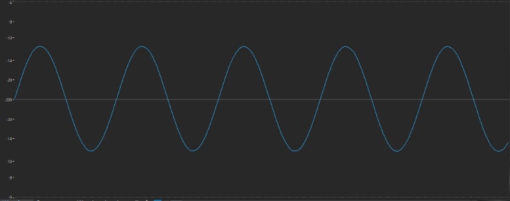
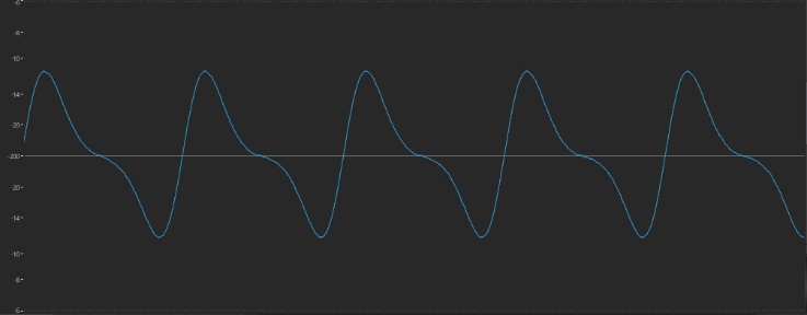
Obviously, the timbre at the end is quite different from the one at the beginning. As we learned in Part 2, the starting signal (that of the carrier alone, before it is modulated) is a sine wave, which looks like this:
The wave at the end, however, looks quite different:
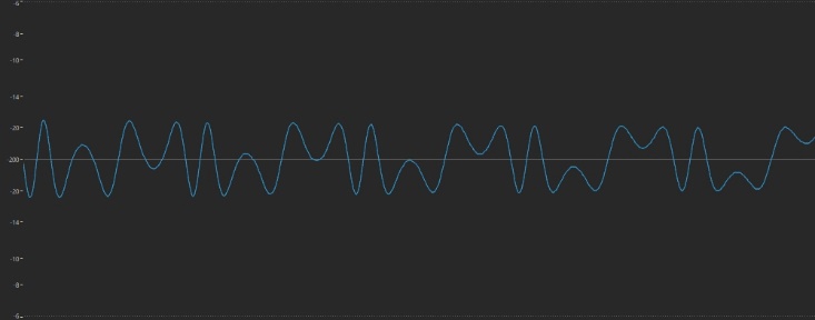
In-between, too, the waveshape has undergone several transformations, at one point looking very much like the traditional sawtooth wave provided by the oscillators in most analog synths:
What happens if we alter the Ratio value of one of the operators? Let’s try it:
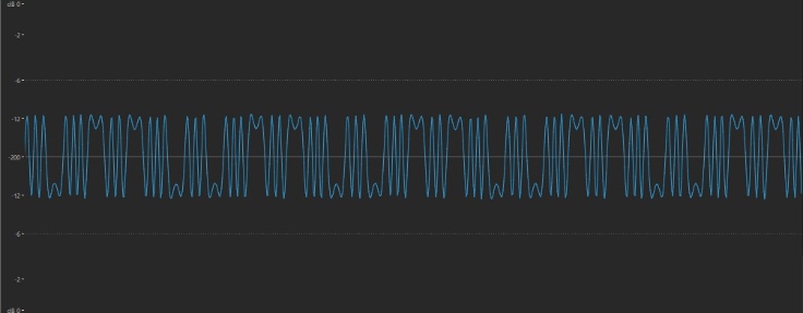
- Return the level of Operator 1 to its minimum value of 0 and then touch the Form/Freq tab at the left-hand side of the screen. Set its Coarse value to 2.00 (for a ratio of 2:1) and slowly raise its level to the maximum value of 99, listening carefully as you do so. This is the sweep you’ll hear:
This time, the waveform at the end is considerably more complex than in our last experiment, indicating the presence of more overtones:
Perhaps even more intriguing is the shape of the waveform when the Level is set to a value of 66:
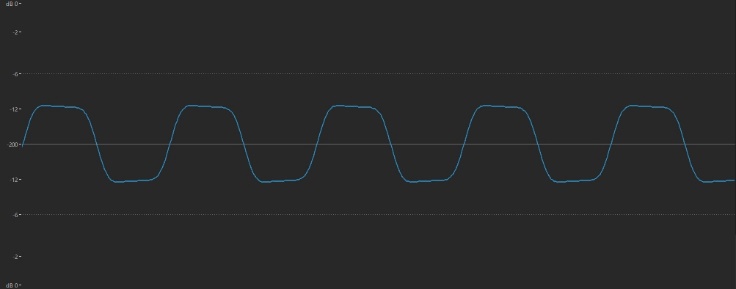
This looks very much like the square wave most analog synth oscillators offer. It’s a waveform that’s typically used to fashion woodwind-like sounds (just as sawtooth waves are used to fashion brass sounds), and it sounds like this:
If you’d like to try it out for yourself, you can download the Performance named “Part 3_05” from Soundmondo. Played in context, it sounds somewhat clarinetish … although, as we’ll learn in the next installment of this series, we can get it a lot closer to clarinet when we start tweaking envelopes.
Curious as to what happens when you raise the Ratio of the modulator (Operator 1, in this case) even further? Try changing it to values of 3.00, 4.00, and higher, each time slowly raising Operator 1’s level so that you can hear the sonic differences. Here’s what the sweep at a ratio of 3:1 sounds like:
Compare it to what you hear with a ratio of 6:1:
Of course, you can stop the sweep at any time when you discover a useful timbre, at which point you should save it as a Performance for future use in your musical creations. For example, here’s the tonality you get (this is downloadable from Soundmondo as the Performance named “Part 3_06”) when you set the ratio to 6:1 and set Operator 1’s Level to a value of 77:
As you might expect (and as you can clearly hear), the higher the ratio (that is, the greater the difference between the frequency of the modulator and that of the carrier), the higher the overtones generated. But keen-eared listeners will notice a kind of sonic weirdness when increasing modulator levels to near maximum when using high ratios. This a form of digital distortion called aliasing, the result of overloading, a byproduct of which is the production of inharmonic overtones (as discussed in Part 2, these are overtones that are not exact multiples of the fundamental frequency, but instead have only a random relationship).
Inharmonic overtones are the essence of clangorous sounds like bells, chimes, cymbals, etc.—all sounds that digital FM synths are especially good at creating. More importantly, the digital FM process gives you a great deal of control over which inharmonics are generated, as well as their strength, allowing you to precisely craft the sounds you want to hear. Let’s find out how to pull off this feat of sonic wizardry.
Non-Integer Ratio Modulation
The key to creating sounds with inharmonics is to use non-integer (non-whole number) ratios between modulator and carrier—that is, fractional ratios such as 1.01:1, or 3.87:1, or 6.92:1. As occurs when using integer ratios, the higher the ratio, the higher the frequency of the overtones generated (only in this case, the overtones are inharmonics), and the greater the level of the modulator, the greater the strength of the overtones (again, in this case, inharmonics) generated.
Let’s see how this works. Call up the “Part 3_01” Performance you created earlier (or download it from SoundMondo) and do the following:
- Press [EDIT]
- Press [PART SELECT 1/1]
- Touch the OP1 tab at the bottom of the screen or press the [MOTION SEQ SELECT 1] button
- Touch the Level tab on the left-hand side of the screen and set the level of Operator 1 to 99
- Touch the Form/Freq tab in the upper left-hand corner of the screen
- Touch the Fine box, and play middle C on your keyboard, then use the INC/YES button to increase the Ratio value to 1.01. The buzzy sound you hear starts beating when you press the button:
- Play the C above Middle C on your keyboard. Note that the beating is occurring twice as fast. Now play Middle C again, followed by the C below middle C. This time, the beating rate is halved. This change in beat rate (doubling and halving per octave) is occurring because both the modulator and carrier are tracking the keyboard; the higher the note you play, the faster the beating.
- Use the INC/YES button or data dial to continue increasing the Fine value, holding down Middle C on the keyboard and listening as you do so. This is the sweep you’ll hear:
Clearly, as this (non-integer) ratio increases, so too does the frequency of the inharmonic overtones being generated; in other words, their type changes. (At a certain point, you even begin hearing undertones—inharmonics below the fundamental frequency; the reason for this is mathematically complicated and beyond the scope of this article, but it’s worth noting.) At the highest Fine value of 127 (which results in a ratio of 1.99: 1), you hear beating once again because the ratio is close to being an integer value (in this case, 2:1).
As we’ve mentioned before, you can stop the sweep at any time when you discover a useful timbre. For example, here’s the tonality you get when you set Operator 1’s Fine value to 64 (for a ratio to 1.64:1) and set its Level value to 70:
Clearly, this is a very percussive sound (although, again, we can get it a lot closer when we start tweaking envelopes, as we’ll be doing in the next installment in this series), due in large part to the presence of a lot of inharmonic overtones. Before moving on, take a moment to save this Performance as “Part 3_07” (downloadable from Soundmondo) and then continue experimenting with different non-integer ratios between Operator 1 (the modulator) and Operator 2 (the carrier), tweaking the Level of Operator 1 as you do so in order to discover tonalities that might be useful to you in your musical endeavors. Again, you’ll find confirmation of these two guiding principles of frequency modulation: the higher the modulator/carrier ratio, the higher the frequency of the overtones, and the greater the modulator level, the more overtones.
Before we leave the subject of modulation, however, we have one more important parameter to discuss. It’s called …
Feedback
As we mentioned earlier in this article, every algorithm has a line around one of the operators called a feedback loop. This indicates that the output of the operator in question (which is almost always a modulator, the exceptions being Algorithm 1 and Algorithm 55) can be routed back to its own input. (The DX7 offered a couple of algorithms whereby the output of an operator could be fed back into the input of a different operator, but since that feature had little practical value, none of the algorithms in modern digital FM instruments like MONTAGE or MODX offer this capability.)
The purpose of feedback in the digital FM process is to allow a single operator to output a more complex wave than a simple sine wave. Since by definition the ratio between an operator and itself can only ever be 1:1 (think about it), the wave being generated is exactly the same as using a 1:1 modulator/carrier ratio … but with the use of only one operator instead of two. Unfortunately, the Feedback parameter only has a range of 0 – 7 (as opposed to the Level parameter, which has a range of 0 – 127), so there are only 6 different degrees of feedback to choose from. Nonetheless, it is, as John Chowning has said, “a simple but very effective way to get an ‘edge’ to cut through.”
Let’s see how it works:
- Begin by calling up the “Part 2_01” Performance you created in Part 2 of this series, or click here to download it from Soundmondo. (This is simply “Init Normal (FM-X),” saved without reverb.)
- Press [EDIT]
- Press [PART SELECT 1/1]
- Touch the OP1 tab at the bottom of the screen or press the [MOTION SEQ SELECT 1] button
- Touch the Common tab at the bottom of the screen, then touch the Algorithm tab on the left-hand side of the screen. Note that Algorithm 1 is being used—a configuration where all eight operators are being used as carriers, with the feedback loop on Operator 1:

- Touch the Feedback box in the screen (circled in red in the illustration below) to select it.
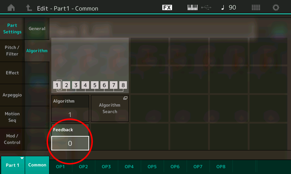
- Use the INC/YES button or data dial to slowly increase the Feedback value to its maximum of 7, holding down a note on the keyboard and listening as you do so. This is what you’ll hear:
Not very exciting, is it? All you’re really hearing is a simple sine wave slowly getting buzzier, similar to what happens when you raise the output of a modulator to its maximum value in a 1:1 ratio with a carrier. But it’s what happens at the endpoint—when the Feedback value reaches its maximum of 7—that’s of interest. Here’s what that waveform looks like:
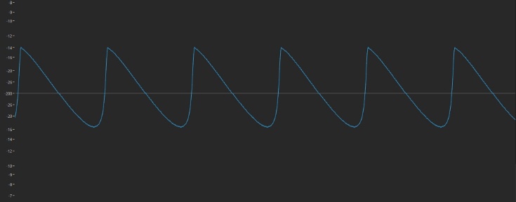
This is a nearly perfect digital replica of the traditional sawtooth wave offered by the oscillators in most analog synths—even better, in fact, than the one we achieved earlier, when we set up a 1:1 ratio between a modulator and carrier and raised the modulator level to around its midpoint.
So now we know what happens when the Feedback value is set to maximum: the operator outputs a sawtooth wave instead of a sine wave. If the feedback loop is on a modulator (as it is in most algorithms), this means that you’ll be modulating with a sawtooth wave instead of a sine wave. If your guess is that the end result will be even more complexity in the timbre created, you’re absolutely right. Let’s try it out:
- Call up the “Part 3_01” Performance you created earlier, or download it from SoundMondo website. (This is the same as the “Part 2_01” Performance, but with Algorithm 67 selected and the levels of Operators 1 and 2 set to 0 and 99, respectively.)
- Press [EDIT]
- Press [PART SELECT 1/1]
- Touch the OP1 tab at the bottom of the screen or press the [MOTION SEQ SELECT 1] button
- Touch the Common tab at the bottom of the screen, then touch the Algorithm tab on the left-hand side of the screen. Note that Algorithm 67 is being used, with the feedback loop again on Operator 1 … only in this configuration, Operator 1 is acting as a modulator instead of a carrier.

- Touch the OP1 tab at the bottom of the screen, then touch the Level tab at the left-hand side of the screen
- Touch the Level box and use the INC/YES button or data dial to set the value to 99 (this will allow us to hear the effect of the Feedback parameter)
- Touch the Common tab at the bottom of the screen, then touch the Algorithm tab on the left-hand side of the screen
- Touch the Feedback box and use the INC/YES button or data dial to slowly increase the Feedback value to its maximum of 7, holding down a note on the keyboard and listening as you do so. This is what you’ll hear:
What a difference! This time you hear a complex wave (the result of Operator 1 modulating Operator 2 at maximum level) getting ever more complex, until it generates into a hash of noise, the result of the generation of a ton of overtones completely obliterating the source sound. Now you know how to create noise on a digital FM synth! (Ever need noise in your musical explorations? Store this Performance as “Part 3_08”—also downloadable from SoundMondo—for future use.)
As you might expect, feedback has an ever greater effect as you increase the modulator/carrier ratio, and also can cause the production of interesting complex inharmonics when used with non-integer ratios. Try it! You may just come up with some great starter sounds … sounds that can only get better and more interesting as you apply envelopes to them. Join us here for Part 4 as we do just that.
Have questions/comments? Join the conversation on the Forum here.
Missed any part of the series? Click on the links below:
FM 101, Part One: Discovering Digital FM…John Chowning Remembers
FM 101, Part Two: The Basics
Ready to move on? Check out the next article in the series FM 101, Part 4: Going from Static to Dynamic
Tagged Under
Keep Reading
© 2025 Yamaha Corporation of America and Yamaha Corporation. All rights reserved. Terms of Use | Privacy Policy | Contact Us


